IC Realtime Combo Series: 8 Channel DVR with built-in 19 LCD monitor User Manual
Page 28
19
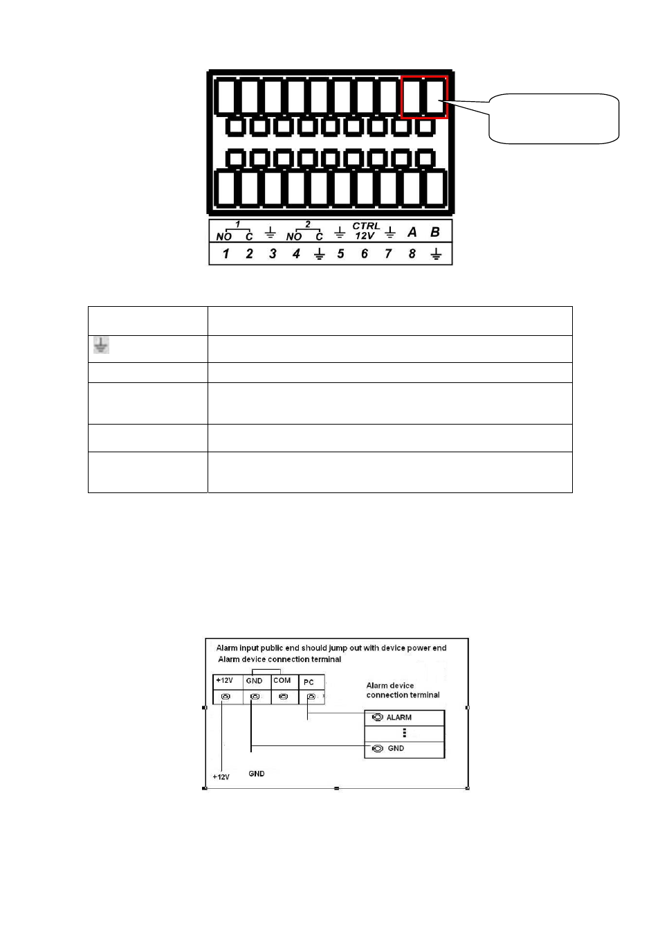
Figure 3-7
Parameter
Grounding Alarm
Ground line
Alarm Input
1, 2, …, 8. It becomes valid in low voltage.
1-NO C,
2-NO C,
Two NO activation outputs.
CTRL 12V
It Is to control the power output
You need to close the device power to cancel the alarm.
A/B
485 communication port. They are used to control devices such as
PTZ. Please parallel connect 120
T
Ω between A/B cables if there are
too many PTZ decoders.
T
3.8.2 Alarm Input Port
Please refer to the following sheet for more information.
z
Normal open or Normal close type
z
Please parallel connect COM end and GND end of the alarm detector (Provide external
power to the alarm detector).
z
Please parallel connect the Ground of the combo DVR and the ground of the alarm detector.
z
Please connect the NC port of the alarm sensor to the combo DVR alarm input(ALARM)
z
Use the same ground with that of combo DVR if you use external power to the alarm device.
Figure 3-8
3.8.3 Alarm Output Port
AB Connection
port