Finish the model, Install the radio system – Great Planes Yak-54 1.60 ARF - GPMA1411 User Manual
Page 25
cowl back until the ring is fully seated on the drive washer.
(Some engine installations may require you to cut a portion of
the cowl away to clear the engine head in order to fit it onto the
fuselage. Cut away just enough needed to fit the cowl now. A
clean-edged, straight, cooling hole can be more carefully cut
out when finishing the model).
❏
9. Carefully remove the cowl ring from the engine
crankshaft being sure not to disturb the position of the cowl
(masking tape will help hold the cowl in position). Temporarily
secure the cowl ring to the cowl with a couple of dots of
6-minute epoxy. Using the included extra long 3/32" [2.4 mm]
allen key, remove the 4-40 x 1/2" [13 mm] cap head screws
securing the cowl ring to the firewall. Slide the cowl and cowl
ring off of the fuselage as one piece. The friction fit between
the ring, cowl and the epoxy will hold them together.
❏
10. Mix up 1/2 oz. [15 cc] batch of 30-minute epoxy
combined with Top Flite Microballoons Filler (if using a gas
engine, substitute Microballoons Filler with Great Planes
Pro Milled Fiberglass for a stronger joint and make a larger
fillet as described in this step). Make an epoxy fillet along the
front of the cowl ring where it meets the cowl. Do not apply
epoxy to the back of the cowl ring as it will interfere with the
ring sitting flush against the firewall. Let the cowl sit
undisturbed until the epoxy has cured.
❏
1. Install your receiver switch or an optional switch
mounting jack (we used the Great Planes Switch/Charge
Jack Mounting Set, GPMM1000) in a position on the
fuselage so the battery and charge leads are a within reach
of the receiver tray.
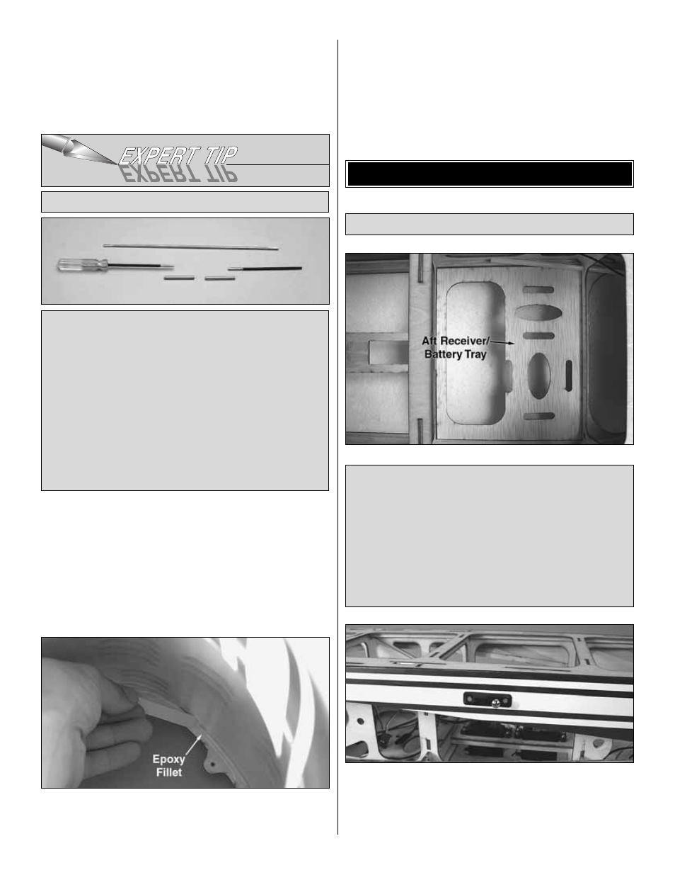
Note: The Yak 54 1.60 ARF includes an optional aft
receiver/battery tray. This tray can be used if the model
requires excessive weight added to the tail in order to balance
within the range specified in the balance section of this
manual. Heavier gas engines will most likely result in required
tail weight. If tail weight is required, fit the optional aft
receiver/battery tray into the fuselage as shown and glue it in
place. Move your radio equipment to the aft tray and
rebalance the model. The servo extensions mentioned earlier
are long enough to reach the aft receiver/battery installation.
Install the Radio System
FINISH THE MODEL
An extra-long 3/32" [2.4 mm] allen wrench is included with
the Yak 54 1.60 ARF to install and remove the cowl
screws. If you would like to make an extended wrench with
a handle rather than the one supplied with an “L”-bend,
one could be made by splicing together a 3/32" [2.4 mm]
ball-end hex wrench with a piece of 4-40 pushrod and 1/8"
[3.2 mm] brass tubing. Use a file to round the ends of the
wrench so they will fit into the brass tubes. Then, hold it all
together with silver solder.
The wrench can be made to any length you like, and is so
useful that it will probably become a permanent addition to
the field box.
Make Your Own Extra-Long Hex Wrench
25