Great Planes Yak-54 1.60 ARF - GPMA1411 User Manual
Page 17
wheels included with the rudder servos (Different model
servos may come with servo wheels that are larger or smaller
than the ones shown in the picture. The actual size of the servo
wheels being used is not critical.) Fit the aluminum servo
extensions to the undersides of the servo wheels and tape
them in place. Use a 1/16" [1.6mm] drill bit to drill through the
four mounting holes in the servo extensions into the plastic
servo wheels. Remove the servo wheels from the extensions
and enlarge the holes with a 3/32" [2.4mm] drill bit.
❏
7. Using eight 2-56 x 3/8" [9.5 mm] Phillips screws and
eight #2 flat washers, attach the servo extensions to the
servo wheels. Apply a drop of thread-locking compound to
each screw. With a cut-off wheel, cut off the ends of the
screws that protrude from underneath the servo extensions.
❏
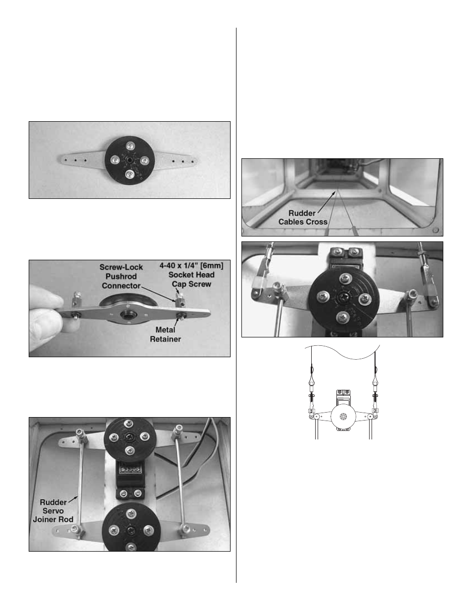
8. Drill out the inner holes of both servo extensions using a
7/64" [2.8 mm] bit. Do not use any other size drill bit for this step.
Secure a screw-lock pushrod connector to each arm in the holes
you just drilled out with a metal retainer. Thread four 4-40 x 1/4"
[6 mm] SHCS loosely into the screw-lock pushrod connectors.
❏
9. With the servos centered, align the servo arms
perpendicular with the fuselage and parallel with each other
and secure them to the rudder servos with the servo arm
screws. Insert the two rudder servo joiner rods (included
with the kit), through the screw-lock pushrod connectors as
shown and tighten the 4-40 x 1/4" [6 mm] SHCS. Use wire
cutters to cut away the excess joiner rod length.
❏
10. Connect the other two clevis ends with the brass
couplers installed onto the outer holes of the aft rudder
servo arm. Check to be sure that the elevator servo wires
are not entangled in the rudder pull-pull cables. Slide a 3"
[76 mm] piece of 1/8" [3 mm] heat-shrink tubing and then a
swage onto the ends of the pull-pull cables inside the
fuselage. Move the rudder to the neutral position and feed
the ends of the cables through the holes in the couplers. The
pull-pull cables will cross each other inside the fuselage.
With both pull-pull cables having tension and the rudder in
the neutral position, crimp the swages onto the cable ends
to secure them as you did in step 4. You can fine-tune the
tension on the lines by threading the clevises up or down on
the couplers until satisfied. Then, tighten the 4-40 nuts
against the clevises.
17