Optional gas engine installation – Great Planes Yak-54 1.60 ARF - GPMA1411 User Manual
Page 21
❏
7. Insert the stopper into the tank and check the length of
the carb line and fill lines. The clunks should rest almost
against the back of the tank when the stopper is in place but
move freely. Adjust the length of the fuel line until the proper
length has been reached. Once you are satisfied with the fit,
secure the stopper using the Phillips head screw in the
stopper assembly. Be careful not to overtighten as the fuel
tank could split.
❏
8. Cut a piece of 1/4" [6.4 mm] foam rubber (not included)
to fit the fuel tank mounting tray. Glue it in place using CA.
Temporarily insert the fuel tank into the fuselage as shown.
❏
9. Drill a hole through the firewall for the carburetor fuel
line to pass through. Use the position of the fuel tank lines
and the fuel inlet on the carburetor to locate the hole. An
extended drill bit can be used, or mark where the hole is to
be drilled and remove the engine from the mount to use a
standard length drill bit. Drill another hole (if you equipped
your fuel tank with a fill line) on the underside of the engine
mounting box for the fill line. The vent line can also be routed
out the underside of the mounting box.
❏
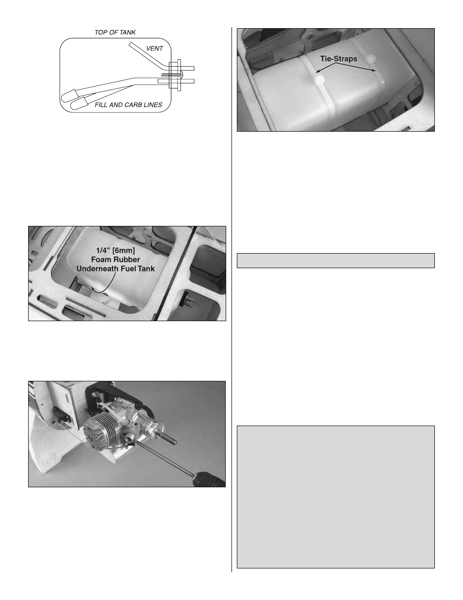
10. Secure the fuel tank to the mounting tray using the
included tie-straps. Align the grooves in the tank with the
grooves cut out of the sides of the mounting tray. Fit the tie-
straps around these grooves.
Note: The fuel line and stopper included in the Great Planes
Yak 54 1.60 ARF are NOT gasoline safe. Gasoline will
degrade the rubber stopper and silicone fuel tubing
supplied. You will need to purchase a gasoline safe stopper
and gasoline safe tubing to use for the fuel system on this
model. The Sullivan #484 Gasoline/Diesel fuel tank
conversion kit (SULQ2684) works well for this. See the
“Fuel Tank Setup” section on page 3.
A mounting template for the Fuji-Imvac BT-43 EI engine is
provided on the back cover page of this manual and pictures
taken show the installation of this model gas engine. If
another model engine is used, the engine manufacturer may
provide a mounting template to use on the firewall. The gas
engine installation will be similar for most model engines.
Because of the possibility of ignition engines creating
radio noise, we use a plastic pushrod for the throttle
servo installation. This isolates the engine and any
radio noise from the servos. This is an IMPORTANT
selection, and we cannot recommend strongly
enough that you DO NOT change this pushrod to a
metal pushrod. All radio equipment – including
throttle servo, receiver battery, electronic kill switch,
receiver on/off switch, servo leads – should be
mounted at least 10" [250 mm] away from anything
related to the ignition/gasoline engine. Any material
used between the engine and the radio equipment is
STRONGLY recommended to be plastic, nylon, or
otherwise non-metallic and nonconductive to
minimize ignition noise transmission.
Optional Gas Engine Installation
21