Great Planes Yak-54 1.60 ARF - GPMA1411 User Manual
Page 18
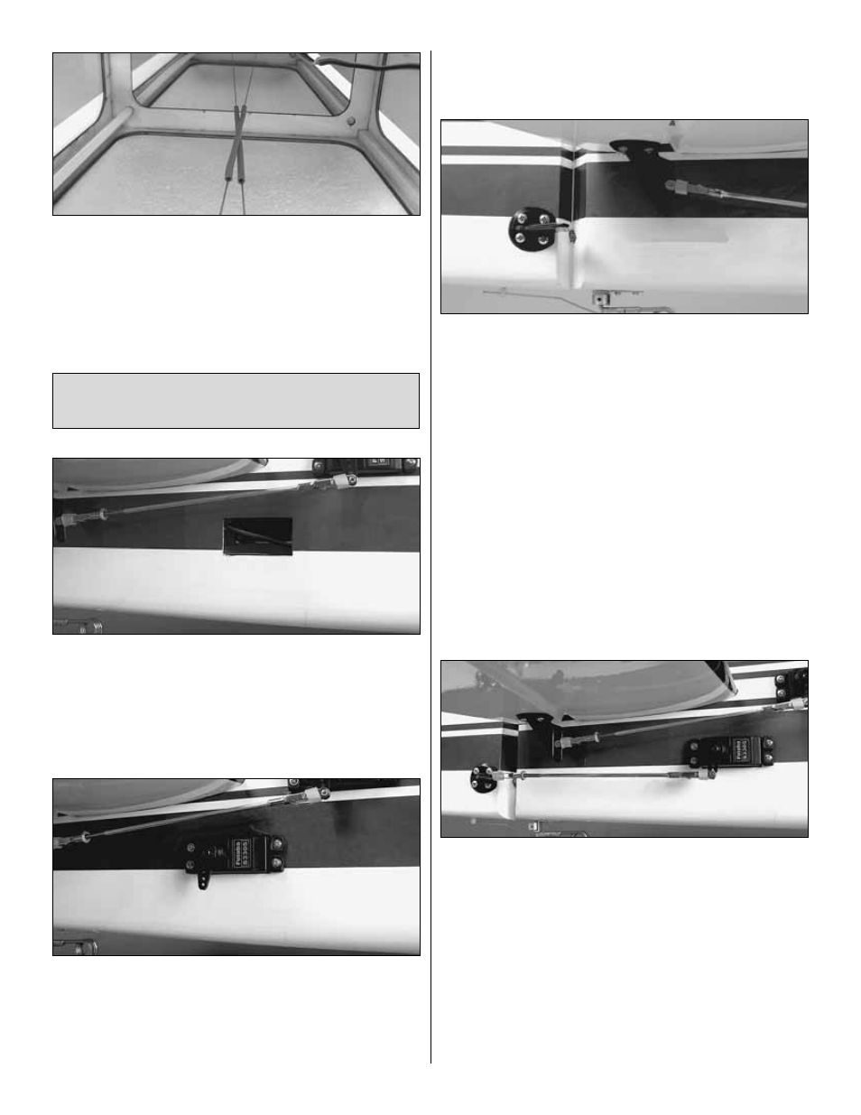
❏
11. Apply heat to the heat-shrink tubing on the cables.
Slide the heat-shrink down the cables toward the tail,
centering the pieces on the location where the cables cross
each other. This will prevent the metal cables from rubbing
against each other which could cause radio interference.
With the heat-shrink tubes in place, use medium CA glue to
adhere the heat-shrink to the cables. Be careful not to glue
the heat-shrink tubes to each other.
❏
1. Locate the cutouts for the rudder servos on both sides
of the fuselage beneath the horizontal stabilizer. Cut the
covering 1/8" [3 mm] inside the openings. Use a trim iron to
seal the covering to the inner edges of the opening.
❏
2. Attach a 36" [914 mm] servo extension to each elevator
servo. Secure the connections with heat-shrink tubing.
❏
3. Temporarily position the rudder servos into the servo
bays. Drill a 1/16" [1.6 mm] hole through the four mounting
holes of each servo, drilling through the plywood mounting
plates in the fuselage. Install and remove a servo mounting
screw into each of the eight holes. Apply a drop of thin CA
into the holes to harden the wood. After the glue has cured,
install the servos into the openings using the hardware that
came with your servos. Center the servos with your radio
system and install servo arms as shown.
❏
4. Just as you did with the ailerons, look closely on the
sides of the rudder and you will notice a plywood plate
visible under the covering. Place a heavy-duty nylon control
horn on each side of the rudder, positioning it as shown and
aligning it with the outer hole of the servo arm. Mark the
location for the screw holes. Drill through the marks you
made with a 3/32" [2.4 mm] drill bit. (Be sure you are drilling
into the plywood plates mounted in the rudder. Drill through
the plate only. Do not drill all the way through the rudder!)
Using a #4 x 5/8" [16 mm] sheet metal screw, install and
then remove a screw into each of the holes. Harden the
holes with thin CA. Install the control horns with eight #4 x
5/8" [16 mm] sheet metal screws.
❏
5. Locate two .095" x 12" [2.4 x 305 mm] pushrod wires
threaded on one end. Thread a 4-40 nut, a silicone clevis
retainer and a threaded metal clevis onto the threaded ends
of the wires 20 turns. Tighten the nut against the clevis and
then install the clevis on the rudder control horns.
❏
6. Be sure the rudder servos are centered (with the arms
pointing down). Install a 4-40 metal solder clevis onto the
outer most hole in each servo arm. Center the servo arms
and center the rudder. Using the solder clevis as a guide,
mark where to cut the pushrod wire. Remove the pushrods
and clevises from the control horns and the solder clevises
from the servo arms. Cut the pushrod to length, install
another silicone clevis retainer, and solder the clevises to
the pushrods.
Install the Rudder Servos & Linkage
(Recommended Gas Engine Installation)
18