Great Planes Yak-54 1.60 ARF - GPMA1411 User Manual
Page 20
❏
3. Install a servo arm downward and angled towards the
rear of the plane.
❏
4. If you have not already done so, install the muffler for
your engine. The throttle pushrod will need to be routed so it
will clear the muffler.
❏
5. Install a brass screw-lock pushrod connector, nylon
retainer ring and a 4-40 x 1/4" [6 mm] SHCS onto the outer
hole of the servo arm. Bend a .074 x 12" [305 mm] threaded
rod to fit from the throttle servo arm to the throttle carburetor
arm. When bending the wire, be sure that you have clearance
between the pushrod and any of the engine/muffler
components. Metal contact may create radio interference.
Thread a 2-56 nylon clevis and silicone clevis retainer onto the
threaded rod and connect it to the carburetor.
❏
6. Using your radio system, adjust the throttle servo and
carburetor arm movement as desired.
❏
1. Locate the fuel tank. The hardware needed for the fuel
tank assembly is inside of the tank. Remove the stopper and
shake out the contents.
❏
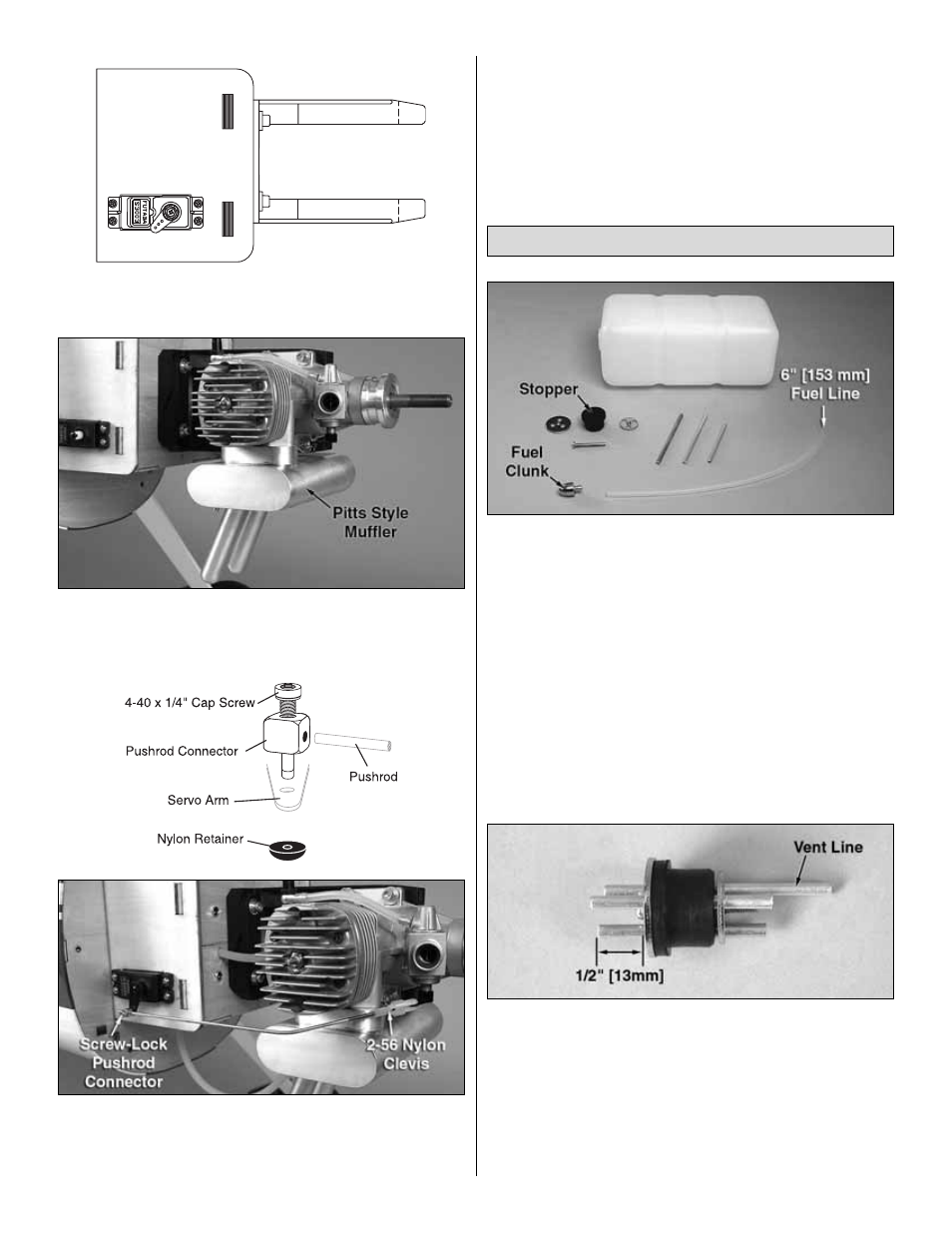
2. The fuel system for the Yak 54 1.60 ARF utilizes a three
line system. There is a fill and drain line, carb line, and vent
line (to muffler). The fill and drain line will allow fueling and
defueling without removing the cowl. The fill line is optional
and may be omitted if desired.
❏
3. Slide the three aluminum fuel tubes into the rubber stopper.
❏
4. Cut the fill line and carb line tubes such that the tubes
extend 1/2" [13 mm] out from both ends of the stopper. The
vent line should be bent upwards and left uncut.
❏
5. Install the metal plates on the front and back of the
stopper and loosely thread the 3 x 26mm [1"] Phillips screw
through the plates.
❏
6. Attach a silicone fuel line 6" [153 mm] in length to the
carb tube on the stopper. Install the included fuel clunk onto
this line. If you want to have the ability to drain the fuel tank
through the fill line, install another piece of silicone fuel line
and a fuel clunk onto the fill line.
Install the Fuel Tank (Glow Engine)
20