Finish the wing – Great Planes Yak-54 1.60 ARF - GPMA1411 User Manual
Page 10
drill all the way through the aileron!) Using a #4 x 5/8" [16 mm]
sheet metal screw, install and then remove a screw into each of
the holes. Harden the holes with thin CA. Install the control horn
with four #4 x 5/8" [16 mm] sheet metal screws.
❏ ❏
7. Locate a .095" x 12" [2.4 x 305 mm] pushrod wire
threaded on one end. Thread a 4-40 nut, a silicone clevis
retainer and a threaded metal clevis onto the threaded end
of the wire 20 turns. Tighten the nut against the clevis and
then install the clevis on the middle hole of the aileron
control horn.
❏ ❏
8. Be sure the aileron servo is centered. Install a 4-40
metal solder clevis onto the outer most hole in the servo
arm. Center the servo arm and center the aileron. Using the
solder clevis as a guide, mark where to cut the pushrod wire.
Remove the pushrod and clevis from the control horn and
the solder clevis from the servo arm. Cut the pushrod to
length. Install another silicone clevis retainer onto the wire
and solder the clevis to the pushrod using the
Expert Tip
that follows.
❏ ❏
9. Install the pushrod and clevises to the outer hole in
the servo arm and the middle hole in the control horn. Adjust
the linkage until the aileron and the servo arm are both
centered. Then, tighten the nut against the clevis. Slide the
two silicone clevis retainers to the end of each clevis.
❏
10. Repeat these steps for the right wing panel.
❏
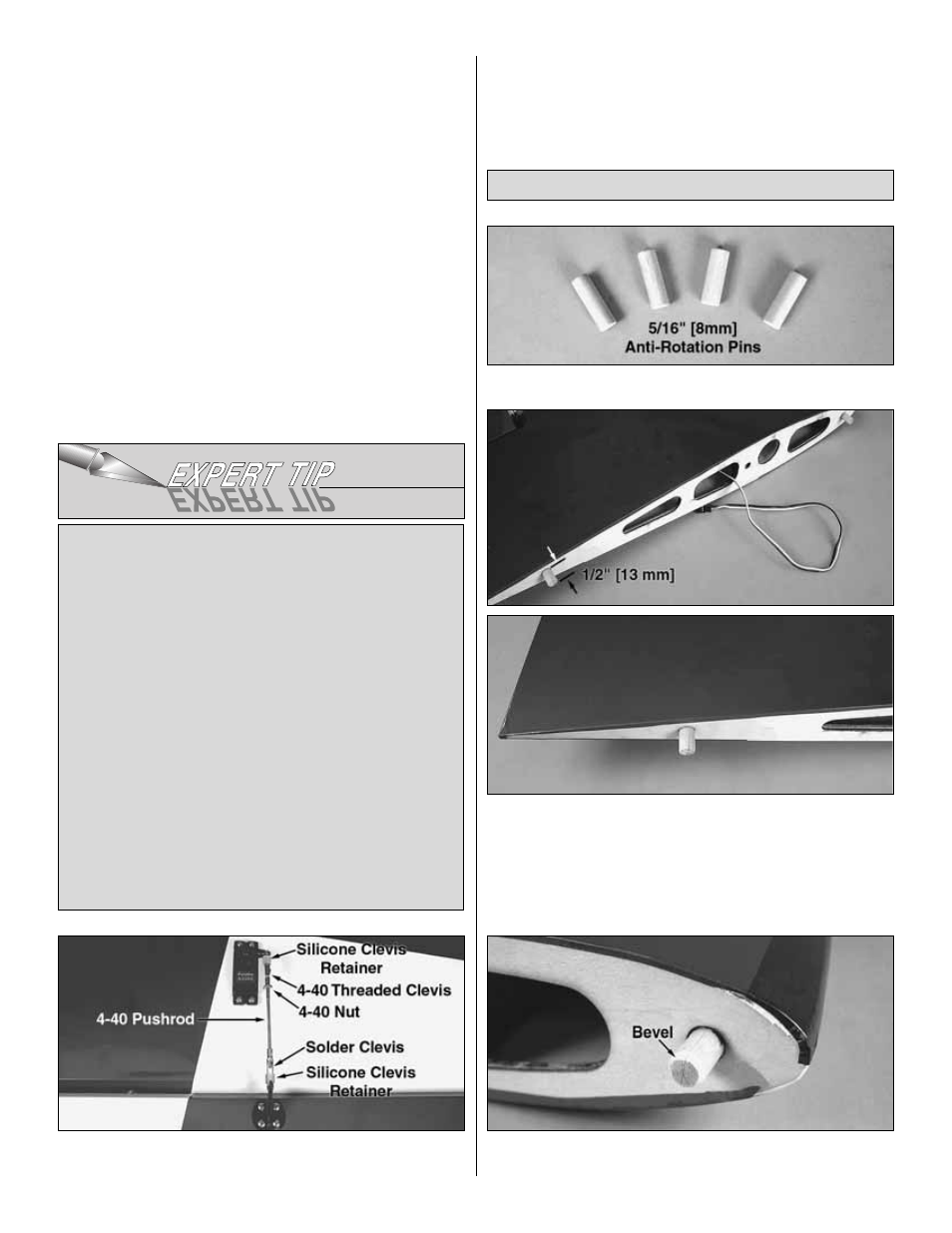
1. Locate the four 5/16" [8 mm] diameter anti-rotation pins.
❏
2. Using 6-minute epoxy, coat half of the anti-rotation pins
and insert them into the forward and aft holes in the wing
panel root ribs. It may be necessary to carefully tap them
into place. The pins should extend out approximately 1/2"
[13 mm]. Wipe away any excess epoxy with a paper towel
and denatured alcohol before the epoxy cures.
❏
3. Use sandpaper to bevel the ends of the anti-rotation
pins to ease their insertion into the fuselage.
Finish the Wing
How to solder the clevis to the pushrod
1. Where the pushrod will make contact with the solder
clevis, roughen the wire with 220-grit sandpaper.
2. Use a denatured alcohol to remove any oil residue
from the wire pushrod.
3. Apply a couple of drops of flux to the wire. Slide the
solder clevis onto the wire. Using a small torch or
soldering iron, heat the wire, allowing the heated wire
to heat the solder clevis. Apply a small amount of
solder to the joint. When the wire and clevis are hot
enough, the solder will flow into the joint. Avoid using
too much solder, causing solder to flow out of the joint
and clump. Use just enough solder to make a good
joint. Allow the wire and clevis to cool.
4. Put a couple of drops of oil onto a rag and wipe the
joint. This will prevent rust from forming on the joint.
10