Great Planes Yak-54 1.60 ARF - GPMA1411 User Manual
Page 15
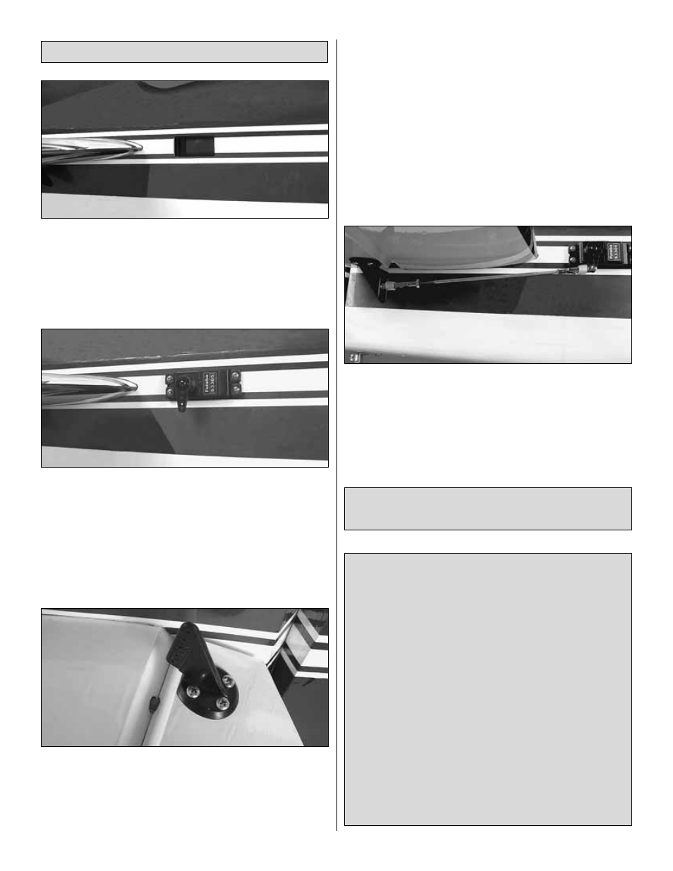
❏
1. Locate the cutouts for the elevator servos on both
sides of the fuselage just forward of the horizontal stabilizer.
Cut the covering 1/8" [3mm] inside the openings. Use a trim
iron to seal the covering to the inner edges of the opening.
❏
2. Attach a 36" [914 mm] servo extension to each elevator
servo. Secure the connections with heat-shrink tubing.
❏
3. Temporarily position the elevator servos into the servo
bays. Drill a 1/16" [1.6 mm] hole through the four mounting
holes of each servo, drilling through the plywood mounting
plates in the fuselage. Install and remove a servo mounting
screw into each of the eight holes. Apply a drop of thin CA
into the holes to harden the wood. After the glue has cured,
install the servos into the openings using the hardware that
came with your servos. Center the servos with your radio
system and install servo arms as shown.
❏
4. Just as you did with the ailerons, look closely on the
bottom of the elevators and you will notice a plywood plate
visible under the covering. Place a heavy-duty nylon control
horn on each of the elevators, positioning it as shown and
aligning it with the servo arm. Mark the location for the screw
holes. Drill through the marks you made with a 3/32" [2.4
mm] drill bit. (Be sure you are drilling into the plywood plates
mounted in the bottom of the elevators. Drill through the
plate only. Do not drill all the way through the elevators!)
Using a #4 x 5/8" [16 mm] sheet metal screw, install and
then remove a screw into each of the holes. Harden the
holes with thin CA. Install the control horns with eight #4 x
5/8" [16 mm] sheet metal screws.
❏
5. Locate two .095" x 12" [2.4 x 305 mm] pushrod wires
threaded on one end. Thread a 4-40 nut, a silicone clevis
retainer and a threaded metal clevis onto the threaded ends
of the wires 20 turns. Tighten the nut against the clevis and
then install the clevis on the elevator control horns.
❏
6. Be sure the elevator servos are centered. Install a 4-40
metal solder clevis onto the outer most hole in each servo arm.
Center the servo arms and center the elevators. Using the
solder clevis as a guide, mark where to cut the pushrod wire.
Remove the pushrods and clevises from the control horns and
the solder clevises from the servo arms. Cut the pushrod to
length, install another silicone clevis retainer, and solder the
clevises to the pushrods.
Important! Please Read Before Installing the Rudder
Servos. This model has the option of two different rudder
servo installations. This is to help balance the airplane and
accommodate different engine weights. If you are
installing a glow engine, you most likely will be a little tail
heavy. You will probably wish to install the servos as
shown in the
“Install the Rudder Servos & Linkage
(Recommended Glow Engine Installation)” section that
follows. If you are installing a gasoline engine, you will
most likely need tail weight and should follow the
“Install
the Rudder Servos & Linkage (Recommended Gas
Engine Installation)” section instructions starting on
page 18. Adding dead weight is something we strive not to
do to our models since extra weight detracts from the
performance of the airplane. Take a moment to read
through both installation methods to determine which is
best for your application. If you are unsure which
installation is best for your engine choice you may wish to
skip the installation of the rudder servos at this time and
install them after you balance the airplane.
Install the Rudder Servos & Linkage
(Recommended Glow Engine Installation)
Install the Elevator Servos & Linkage
15