Set the control throws – Great Planes Seawind .60-.91 ARF - GPMA1360 User Manual
Page 21
❏
4. Remove the backing from the foam tape and apply it to
the cabin area of the fuselage.
❏
5. Position the cabin on the fuselage by first inserting the
wood dowel in the hole at the top of the cabin opening. With
the cabin top in position, drill a 1/16" [1.6mm] pilot hole in the
front center of the cabin top and into the fuselage. Enlarge the
hole in the cabin top to 3/32" [2.4mm]. Secure the cabin top to
the fuselage with a #2 x 3/8" [9.5mm] sheet metal screw and
#2 flat washer.
❏
1. Turn on the transmitter and receiver and center the trims.
If necessary, remove the servo arms from the servos and
reposition them so they are centered. Reinstall the screws that
hold on the servo arms.
❏
2. With the transmitter and receiver still on, check all the
control surfaces to see if they are centered. If necessary, adjust
the clevises on the pushrods to center the control surfaces.
❏
3. Make certain that the control surfaces and the carburetor
respond in the correct direction as shown in the diagram. If
any of the controls respond in the wrong direction, use the
servo reversing in the transmitter to reverse the servos
connected to those controls. Be certain the control surfaces
have remained centered. Adjust if necessary.
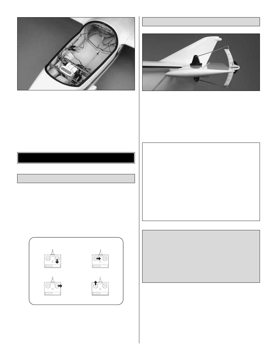
Use a Great Planes AccuThrow (or a ruler) to accurately
measure and set the control throw of each control surface as
indicated in the chart that follows. If your radio does not have
dual rates, we recommend setting the throws at a rate in-
between the high and low rates.
Note: The throws are measured at the widest part of the
elevators, rudder and ailerons.
Note: If you will be flying the Seawind ARF off of water using
the water rudder, once you have the rudder throws set, cut the
excess water rudder control rod when the rudder is at its
maximum throw.
IMPORTANT: The Seawind ARF has been extensively
flown and tested to arrive at the throws at which it flies
best. Flying your model at these throws will provide you
with the greatest chance for successful first flights. If,
after you have become accustomed to the way the
Seawind ARF flies, you would like to change the throws
to suit your taste, that is fine. However, too much control
throw could make the model difficult to control, so
remember, “more is not always better.”
These are the recommended control surface throws:
High Rate
Low Rate
ELEVATOR:
5/8" [16mm] up
7/16" [11mm] up
5/8" [16mm] down
7/16" [11mm] down
RUDDER:
2" [51mm] right
1-1/8" [29mm] right
2" [51mm] left
1-1/8" [29mm] left
AILERONS:
1/2" [13mm] up
3/8" [10mm] up
1/2" [13mm] down
3/8" [10mm] down
FLAPS:
1-1/8" [29mm] down 1/2" [13mm] down
Set the Control Throws
CARBURETOR WIDE OPEN
RUDDER MOVES RIGHT
LEFT AILERON MOVES DOWN
RIGHT AILERON MOVES UP
ELEVATOR MOVES UP
4-CHANNEL
TRANSMITTER
(STANDARD MODE 2)
4-CHANNEL RADIO SETUP
TRANSMITTER
4-CHANNEL
TRANSMITTER
4-CHANNEL
TRANSMITTER
4-CHANNEL
Check the Control Directions
GET THE MODEL READY TO FLY
21