Great Planes PT-E Trainer Electric Kit - GPMA0110 User Manual
Page 21
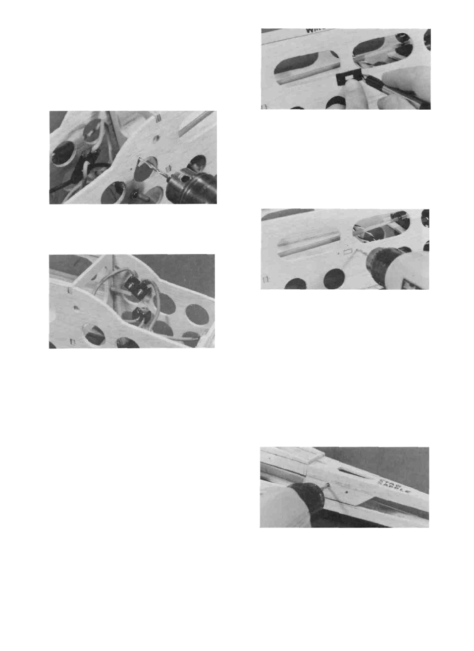
MOUNT THE RECEIVER SWITCH
D 8 When you have determined the correct position
for the micro switch, draw a line around the switch
on the fuselage side for reference.
D 9 Holding the micro switch in place, push a pin
through both holes in the micro switch and out
through the fuselage sides
D 1 Remove the face plate from your receiver switch
and hold it against the outside of the fuselage as
shown in the photo Make sure the switch will be
located above the battery box, and clear of the
on-off switch pushrod!
D 2 Mark the locations of the screw holes and the
rectangular switch hole, using the faceplate as a
guide
D 10 Now drill two 3/32" holes through the fuselage
side at the pin holes Then mount the micro switch
with the two 2-56 x 5/8" screws and nuts
NOTE: Before proceeding, read " Peak Battery
Charging " in the appendix at the back of this book.
NOTE: Remove the propeller from the motor before
testing your electrical system in the next step!
D 11 When you have the motor and switch harness
installed, you may check its operation by hooking
up the motor battery* and activating the toggle
switch The motor should begin running when the
transmitter throttle stick is pushed forward to full
throttle, and stop when the stick is pulled back With
the toggle switch in the "off position, you should
not be able to turn the motor on with the throttle
stick In order for this safety feature to be effec-
tive, you should always keep the toggle switch
in the "off position until just before you are
ready to fly.
*NOTE The motor battery must have a Kyosho-type con-
nector to mate properly with the Thrustmaster switch har-
ness If your battery connector is not compatible, you'll
have to change connectors
D 3. Drill 3/32" holes for the switch mounting screws.
D 4 Use an Xacto knife to cut out the rectangular
switch hole
D 5. Mount the switch to the fuse side and check the
operation (Pushing the switch toward the front
of the airplane is "on"),
CUT PUSHROD EXIT SLOTS
D 1 Study the plan and note the location of the elevator
and rudder pushrod exit slots(they are in the same
location on both sides of the fuselage) Using a ruler,
transfer the locations of these slots from the plan to
the fuselage, marking the front and rear of each slot.
D 2 Drill 1/8" holes in the 3/32" balsa fillers at the
front and rear of the pushrod exit locations
21