Great Planes PT-E Trainer Electric Kit - GPMA0110 User Manual
Page 13
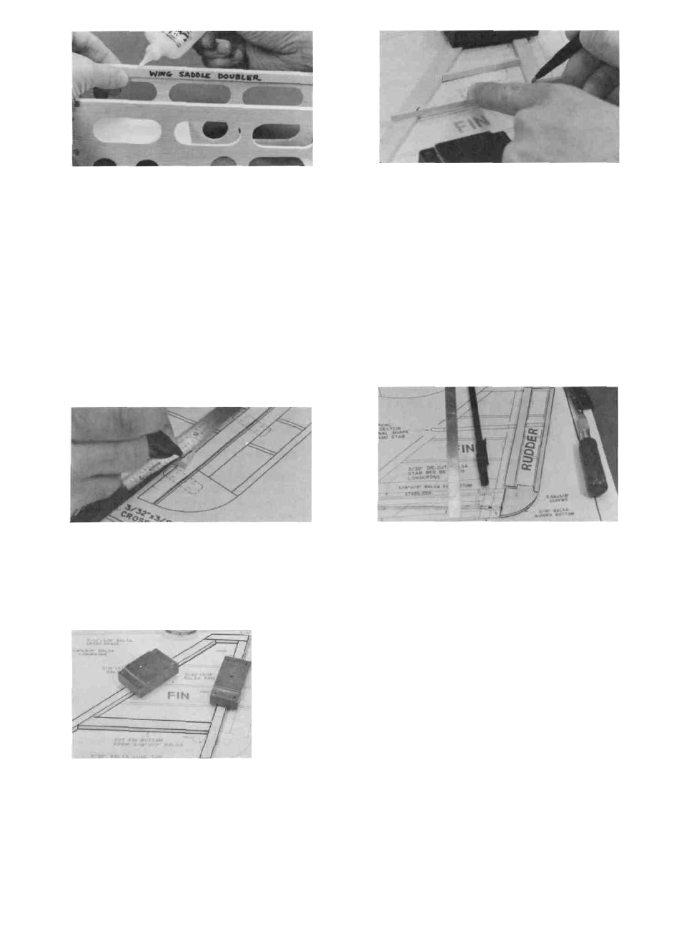
D 15. Find the two 3/32" x 3/8" x 9-1/8" balsa sticks
which you previously marked "Wing Saddle Dou-
bler". Sand the ends of these pieces slightly, to fit
between F-2 and F-3. Glue these doublers in place
with the edge flush with the top edge of the fuse sides.
NOTE: This completes the fuselage assembly for now.
Leaving off the top sheeting will make it easier to install
the other components later.
BUILD THE FIN
1. Find the following parts: 3/16" x 1/2" x 5-1/2" balsa
stick, five 3/16" x 3/8" x 24" balsa sticks, and a 3/32"
x 3/16" x 24" balsa stick. Select the straightest 3/16"
x 3/8" x 24" balsa stick and set it aside for later use
as the stabilizer trailing edge.
D 4. From the 3/32" x 3/16" x 24" balsa stick cut ribs
to fit between the framework, as shown on the plan.
Glue the ribs to the framework.
D 5. Sand both sides of the fin smooth using your T-bar
and 100 grit sandpaper. Sand the leading edge and
top of the fin to a rounded shape as shown in the
typical cross-section.
BUILD THE RUDDER
1. You'll need the following parts: Die-cut 3/16" balsa
rudder bottom, 3/16" x 3/8" x 24" balsa stick, 3/16"
x 3/16" x 24" balsa stick, and a 3/32" x 3/16" balsa
stick.
D
D
2. Working over the separate FIN drawing on the
plan, mark and cut the balsa sticks to make the
outer framework of the fin.Begin by laying one of
the sticks in place, then use a straightedge to mark
the cut-off lines. Cut the stick off with a razor saw,
then proceed to the next part.
D
D
D
D
2. In the same manner as the fin, cut the outer
framework pieces for the rudder.
3. Glue the outer framework and the rudder bottom
together with thin CA. Be sure to work on waxed
paper to avoid gluing the parts to the plan!
4. From the 3/32" x 3/16" balsa stick, cut ribs to fit
between the rudder leading edge and trailing edge.
Glue the ribs in place.
5. Sand both sides of the rudder smooth and flat.
Sand the upper rear corners of the rudder to a round
shape as shown on the plan. Sand the trailing edge
and rudder bottom to a rounded shape as shown in
the typical cross-section.
D
3. Hold or pin the parts over the plan and glue the
outer framework pieces together with thin CA, work-
ing on waxed paper to prevent gluing to the plan.
13