Great Planes PT-E Trainer Electric Kit - GPMA0110 User Manual
Page 12
D 8. Now get the following parts together: Die-cut 3/32"
balsa fuse bottom, formers F-4, F-5 and F-6, and
the die-cut 3/32" balsa stab saddle.
D 9. Work the 3/32" balsa fuse bottom into place
between the bottom longerons. The front of the fuse
bottom must touch the rear of the landing gear plate.
With the fuse upright on a piece of waxed paper,
make sure the fuse bottom is even with the bot-
tom edge of the fuse sides and bottom longerons,
then apply thin CA glue along the bottom joints,
pulling the bottom longerons together. Note: If you
have small hands and are unable to hold the stringers
together, you may use books or other square weights
to hold the longerons together.
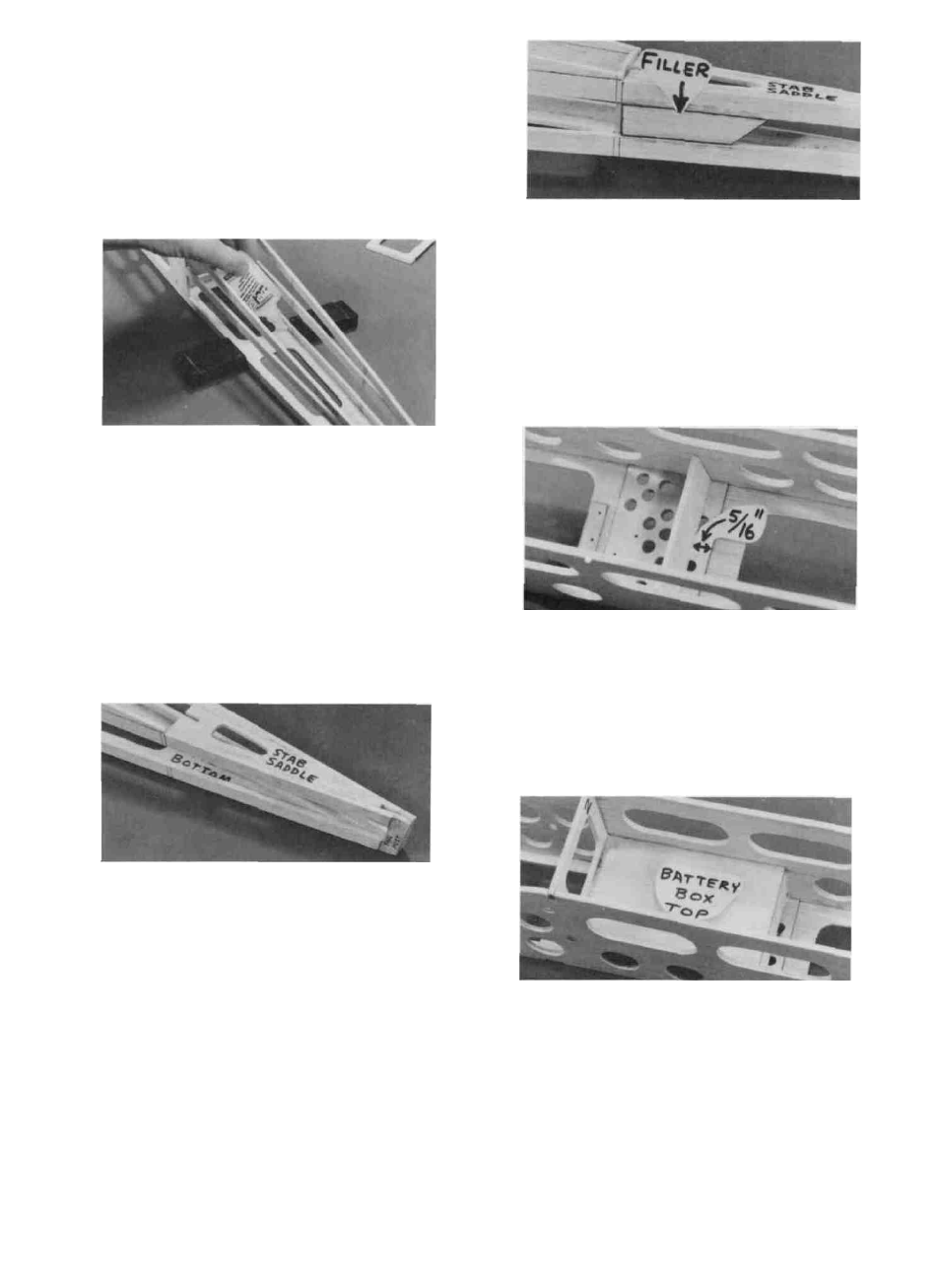
D 12. Find the two die-cut 3/32" balsa pushrod exit
fillers, sand them to fit between the middle and lower
longerons just behind F-6. Glue them in place, flush
with the outside edge of the longerons.
D 13. Find the 3/32" x 1-1/4" x 2-1/2" balsa battery
box rear, and glue it to the landing gear plate, 5/16"
forward of the rear edge of the landing gear plate.
D 10. Slide the 3/32" balsa stab saddle into place be-
tween the middle longerons. The front edge of the
stab saddle must line up with the marks you made
for the rear edge of F-6. Make sure the top edge
of the stab saddle is even with the top of the
longerons, and glue it in place with thin CA.
D 11. Install formers F-4, F-5 and F-6 at the locations
you previously marked. Note: you may have to sand
the sides of the formers slightly for a good fit. Glue
the formers to the fuse bottom, then pull the longe-
rons together and glue them to the formers.
D 14. Find the 3/32" x 2-1/2" x 4-1/16" balsa battery
box top. Position it so the bottom front edge is even
with the bottom edge the cross-brace on F-2. Glue it
to F-2, the fuse sides and to the battery box rear.
12