Great Planes PT-E Trainer Electric Kit - GPMA0110 User Manual
Page 19
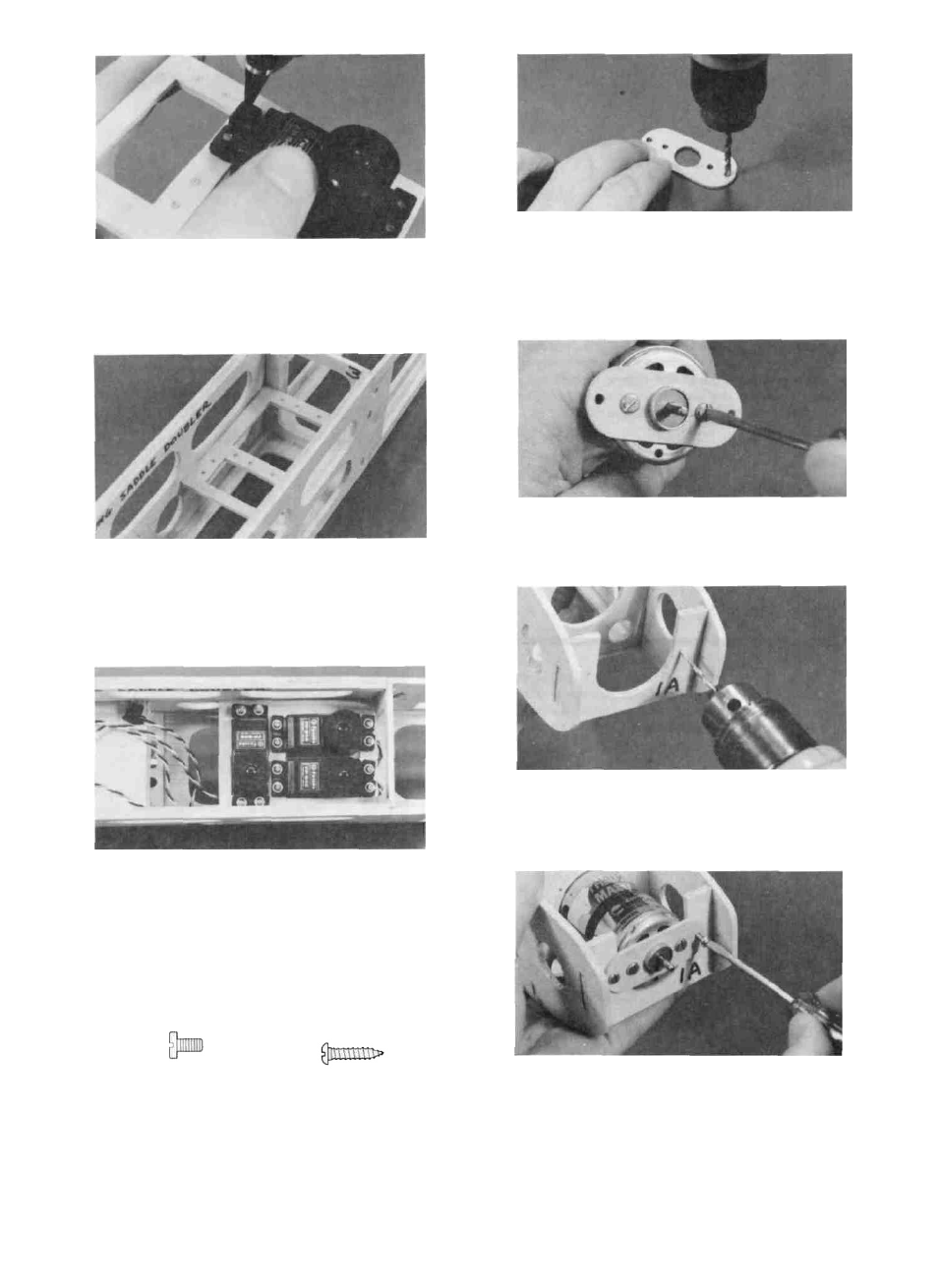
D 3. Holding the servos in place, use a pencil to mark
down through the brass eyelets onto the plywood.
Remove the servos and drill 1/16" holes at each of
the marks.
D 2. Note that we have punched the locations of the
four screw holes in F-1B Drill 1/8" holes at these
four locations. Be sure to use a wood backing
when drilling to prevent damaging the part you are
drilling.
D 3. Mount F-1B onto the front of the motor with the
two M3 x 6 metric screws.
D 4. Study the plan to determine where the servo tray
goes. Glue the servo tray to the fuse sides and to
F-3 with thin CA. Then apply thick CA on top and
bottom of the tray to lock it in place.
D 4. Drill two 5/64" holes in F- 1A at the punched
locations. (These are pilot holes for the #4 x 1/2"
mounting screws).
D 5. Now install the servos into the tray using the
screws provided with your radio.
INSTALL THE MOTOR AND SWITCH HARNESS
D 1. You'll need the following: Electric motor and
switch harness, die- cut 1/16" ply F-1B, two M3 x
6 (metric) screws, and two #4 x 1/2" screws.
M3x6 SCREW # 4 x 1 / 2 " SCREW
D 5. Insert all the switch harness components through
the large hole in F-l, then slide the motor into place.
Secure F-1B to F-1A with the two #4 x 1/2" screws.
19