Great Planes PT-E Trainer Electric Kit - GPMA0110 User Manual
Page 14
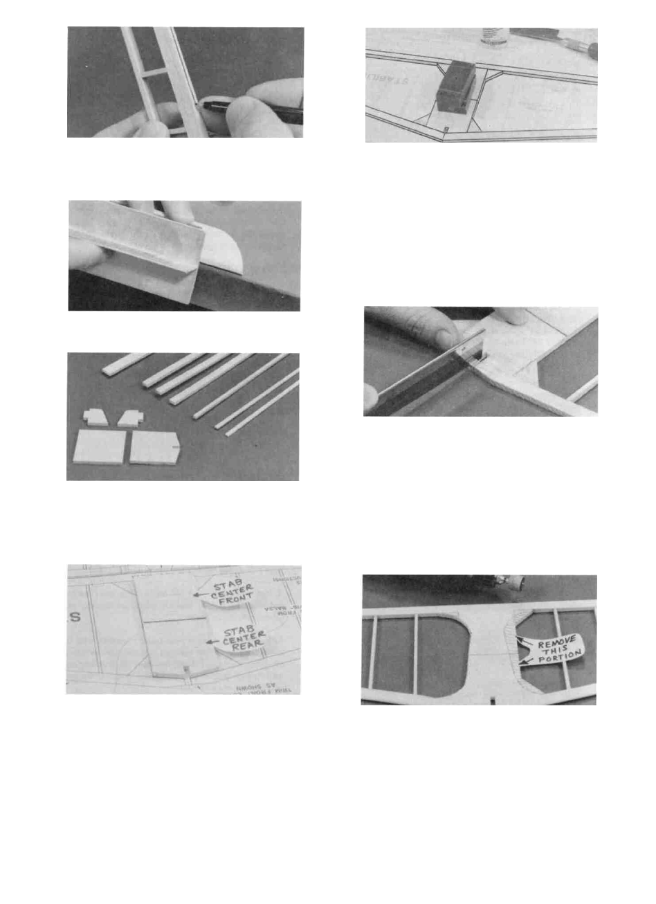
D 6. Draw a centerline down the full length of the
rudder leading edge, then use your T-bar sander to
sand the leading edge to a "V" shape as shown in
the typical cross-section.
BUILD THE STABILIZER
D 1. Get the following items together: Die-cut 3/16"
balsa stab center front and stab center rear, 3/16"
x 3/8" x 24" balsa sticks, 3/32" x 3/16" x 24" balsa
sticks, and the 3/16" x 5/8" x 7" balsa stick. (Note:
The photo also shows the elevator parts).
D 3. From 3/16" x 3/8" balsa sticks, cut the outer
framework pieces and glue them together. Note:
The straightest 3/16" x 3/8" balsa stick should be
used for the trailing edge.
D 4. Cut the triangular corner braces from the 3/16"
x 5/8" x 7" balsa stick and glue them in place.
D 5. Cut the stabilizer ribs from the 3/32" x 3/16" balsa
sticks and glue them in place.
D 6. Cut out the f i n notch in the leading edge, and trim
the front edge as shown on the plan.
D 7. Sand both sides of the stabilizer smooth with your
T-bar, then sand the stabilizer leading edge and ends
to a rounded shape as shown in the typical cross-sec-
tion.
NOTE: If the 3/16" balsa stab center pieces supplied in
your kit are soft balsa (easily dented with your fingernail),
do not perform the next step.
2. Tape a piece of waxed paper over the separate
STABILIZER drawing on the plan, then lay the
die-cut 3/16" balsa stab center pieces on the plan
and pin in place. NOTE: These die-cut pieces may
have irregular edges, so you should sand the edges
with your T- bar first, until they fit the plan exactly.
Edge glue these stab center pieces together with thin
CA.
D 8. Now you may lighten the stabilizer by trimming
the stab center along the dashed line as shown on
the stabilizer drawing. Use your ruler to transfer
the trim lines from the plan to your stabilizer, then
use a Dremel Moto Tool sanding drum or a piece of
sandpaper wrapped around a dowel to sand away the
excess balsa.
14