Great Planes PT-40 Kit (original) User Manual
Page 28
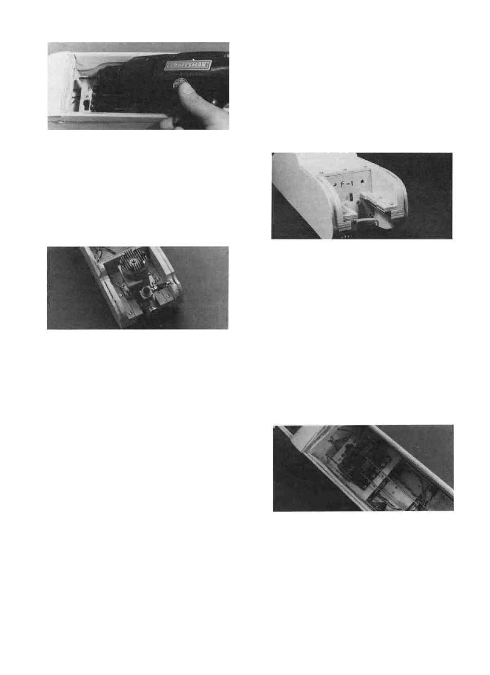
D 29. Use a drill with a 1/8" bit to drill holes through
F-2 for the throttle and nose gear pushrods.
D 30. Bend one of the pushrod wires that has a clevis
attached so it runs freely from the throttle arm on
your engine to the throttle servo.
D 31. Turn on your transmitter and receiver, and
push the throttle stick and the throttle trim tab (left
side of the transmitter) fully forward. Now turn off
the receiver and transmitter (in that order). The servo
arm should now be angled forward about halfway.
D 32. Insert the throttle pushrod through the holes
in F-l and F-2 and attach the nylon clevis to the
throttle arm on your engine.
B-Moving the Z-bend to a different hole in the
servo arm (outer hole gives more movement than
the inner hole).
C- Turning the nylon clevis on the pushrod.
D 36. Re-mount the nose gear bearing, steering arm
and the nose gear.
D 37. Take the final pushrod wire, attach a clevis
and bend the wire to match the nose gear pushrod
drawing on the fuse plan side view, but do not make
the Z-bend yet and do not cut off the excess wire.
D 38. Insert the pushrod through the holes in F-2
and F-l with the clevis at the servo end. Attach the
clevis to the servo wheel.
D 33. With the pushrod in place and the carburetor
wide open, mark the location of the servo arm hole
on the pushrod using an indelible marker.
D 34. Remove the throttle pushrod and make a Z-
bend at the mark you just drew and cut off the excess
wire. Note: To re-insert the throttle pushrod, you will
have to remove the clevis and slide the pushrod in
from the rear. Do so now.
D 35. Turn on the radio and check the operation of
the throttle. With the throttle stick and trim fully
forward the carburetor should be fully open. With
the throttle stick fully back and the trim fully forward
the carburetor should be open just a very small
amount. With the throttle stick and the trim fully
back the carburetor should be fully closed. The servo
must not bind or "buzz" at the full- forward or full-
back positions.
Note: Adjustments made in this set-up are
made by:
A-Moving the clevis to a different hole in the
throttle arm (outer hole gives less movement than
inner hole)
D 39. With the nose gear centered (not turning right
or left), mark the location of the hole in the steering
arm on the pushrod using an indelible marker.
Note: The nose gear pushrod attaches to the
servo wheel on the opposite side of the rudder push
rod attachment.
D 40. Remove the nosegear pushrod and make a
Z-bend at the mark you just made. Cut off the excess
wire.
D 41. Remove the clevis and re-insert the nose gear
pushrod through F-l and F-2. Re-install the clevis,
hook it up and check for proper operation.
Note:To attach the Z-Bend to the steering arm,
you must remove the arm from the nose gear first.
Attach the Z-Bend and then put the steering arm
back in place. Adjustments to re-center the nose
wheel are made by turning the clevis at the servo
end of the pushrod.
If you built Wing A, skip to the next section.
D 42. Temporarily tape the aileron servo mount in
place on the bottom of the wing.
28