Great Planes PT-40 Kit (original) User Manual
Page 15
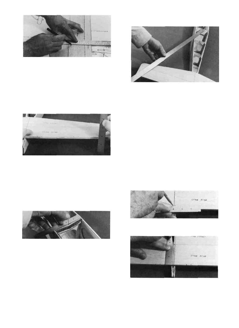
the stab slightly until both measurements are the
same within 1/16" .
D 3. With the fuse on a flat surface, lay the stab
in place on the fuselage in the stab saddle area with
the front of the stab touching the rear surface of F-6
and centered side-to-side.
D 4. While holding the stab firmly in place onto
the saddle, measure down to the flat work surface
from both ends of the stab. If one side is higher than
the other, sand the high side of the stab saddle with
your T-bar sanding block and 80 or 100 grit
sandpaper. Replace the stab in the saddle and re-
check the measurements. Continue this process until
the stab is level within 1/16".
NOTE: READ THROUGH AND PRAC-
TICE THE NEXT 6 STEPS (A-F) BEFORE PRO-
CEEDING.
D 5. Now glue the stab securely to the stab saddle
with 5 minute epoxy. (You may perform this step with
5 minute epoxy, but a slower curing epoxy will give
you more time to make sure the alignment is correct.)
It is important that the stab be centered and square
on the fuselage; so, follow this procedure exactly:
A- With a ruler, measure to find the exact center
of the top of F-3. Stick a pin in at this point.
B- Also measure to find the center of the top
of F-6 and mark this point with a pencil.
C- Lay the stab in the saddle and line up the
"fuse centerline" (which you previously drew on top
of the stab) with the mark on F-6 and with the center
joint at the rear of the fuse.
D- Check the "squareness" of the stab by
measuring from the rear corners of both stab tips to
the pin in the center of F-3. Adjust the position of
E- When you finally have the stab accurately
aligned on the fuse, make four little "alignment
marks" on the stab where the leading and trailing
edge of the stab intersect with the outside edges of
the fuse sides. You will use these marks to quickly
and accurately position the stab when gluing it in
place. Now remove the stab.
F- Mix up a batch of epoxy and spread it on the
stab saddle and the back of F-6. Lay the stab in place
using the "alignment marks" for positioning. Before
the glue sets, re-check the measurements in step D.
Hold or pin the stab in place until the glue sets.
MOUNT THE FIN TO THE STAB
Note: Probably the single most troublesome
cause of poor flying models is improper fin alignment.
Therefore, you should take the time and care neces-
sary to do your "best when performing this next set
of steps. Read through the next five steps before
beginning!
D 1. At the front and back of the "fuse centerline"
which you previously drew on the top of the stab,
make accurate marks 1/8" right and left.
D 2. Using a straight edge and a fine point marker,
connect these marks, making two parallel lines, one
on each side of the fuse centerline.
15