Great Planes PT-40 Kit (original) User Manual
Page 11
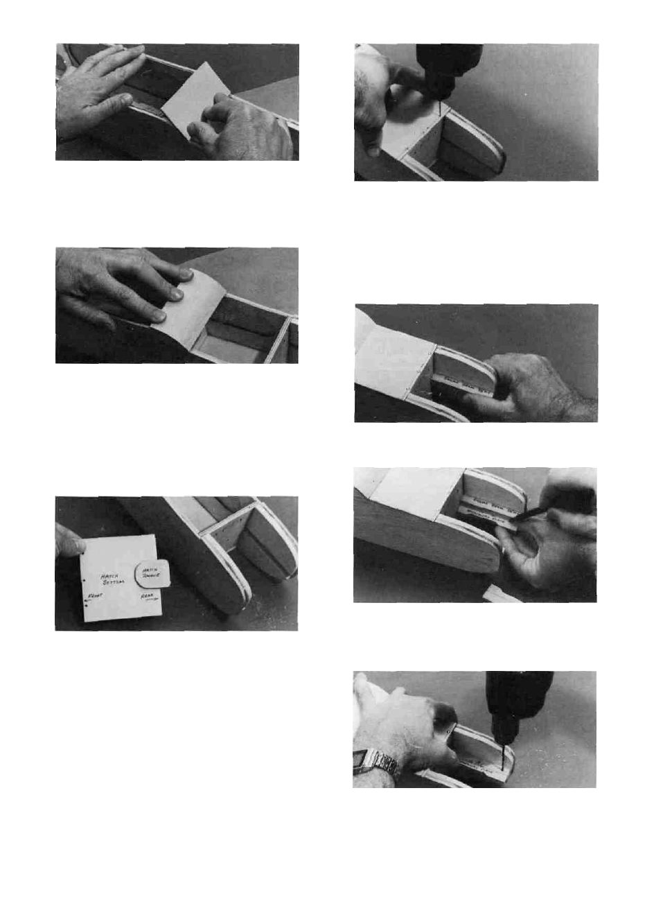
D 5. Wet the top surface of the windshield so the
wood will bend without breaking.
D 6. Apply thick CA to the top of F-2 and the fuse
sides where the windshield will contact, then im-
mediately bend the windshield down and hold until
the glue sets
D 7. Trim any excess windshield even with the back
edge of F-2.
D 8. Taper the rear edge of the 1/8" ply hatch to fit
the windshield as shown on the fuse plan side view.
D 9. Find the piece of 1/8" ply that you punched
out of F-5. This is used as the hatch tongue. Glue the
hatch tongue to the bottom of the 1/8" ply hatch with
thick CA. Let the hatch tongue extend about 1/2"
beyond the back edge of the hatch.
D 10. Draw a guideline 1/8" back from the front edge
of the hatch. This is the centerline of the three hatch
hold down screws.
D 11. Holding the hatch firmly in position, drill three
1/16" holes along the guideline •
D 12. Remove the hatch and re-drill the holes in the
hatch only to 3/32". Then attach the hatch to the fuse
with three #2 x 3/8" screws. (See photo, top of next
column.)
MOUNT THE ENGINE BEAMS AND
BREAKAWAY PLATES
D 1. Glue the 3/8" ply engine beams in place using
5 minute epoxy. With a tissue, wipe off any excess
epoxy that squeezes out when sliding the beams into
the slots. Allow the epoxy to fully cure before disturb-
ing the beams.
D 2. Holding the 1/4" breakaway plate under the
3/8" ply beam, draw a line on the breakaway plate
to mark the edge of the beam.
D 3. Now place the breakaway plate on top of the
beam and while holding the plate firmly in place,
drill three 3/32" holes as shown, drilling down
through the breakaway plate and the beam. Do this
for both plates and beams.
11