Great Planes PT-40 Kit (original) User Manual
Page 24
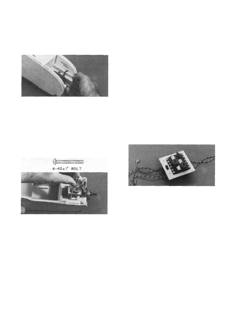
D 8. Screw the breakaway plates down tightly to
the engine beams, and notice two things...
A-Looking at the bottom, do the blind nuts ex-
tend into and between the breakaway plate and the
engine beam?
B-Do the blind nuts stick out into the area
where the engine goes, preventing the engine from
being lowered into place?
D 9. If your answer to A is yes, remove the breaka-
way plates and carefully cut away the top layer of
plywood on the engine beam, in the area where the
blind nut was hitting.
D 10. If your answer to B is yes, use a flat file to file
away the portion of the blind nut that is sticking out
into the engine area.
D 11. Now re-install the breakaway plates. Then
mount the engine to the breakaway plates with the
four 4-40 bolts provided. Note: Later when you install
the engine the final time (before flying), make sure
you slip the small lockwashers on the 4-40 bolts
before mounting the engine.
INSTALL THE SERVOS
Note: The following instructions and photos de-
scribe how to install Futaba S-28 servos in your PT40.
If your radio equipment is different from that shown
in the photos, you may have to use a slightly different
method to mount your servos properly. Be sure to
read the instruction manual for your radio before
beginning this section. If you have difficulty with the
radio installation, ask an experienced model builder
for assistance.
SPECIAL NOTE: Most radio systems sold
today have "servo reversing switches" on the trans-
mitter, which enable the modeler to install the ser-
vos without first checking to determine which direc-
tion the servos rotate. After the installation has been
completed , the modeler merely flips the switches on
the transmitter to make the servos rotate in the de-
sired direction. Many of the older systems, however,
do not have servo reversing...instead they include one
or two "reverse" or "left-handed" servos which rotate
in a direction opposite that of the other servos. When
installing the servos from a system that does not
have servo reversing, you must plan ahead to use
the "reverse" servos where they are needed.
D 1. Prepare the servos (3 are required if you built
Wing A, 4 if you built Wing B) by installing the four
rubber grommets into each servo, then inserting the
brass eyelets up into the grommets.
D 2. Place the servos in the 1/8" plywood servo tray
provided, and space them out so they are not touching
each other or the sides of the opening.
D 3. Holding the servos in place, use a pencil to
mark down through the brass eyelets onto the
plywood. Remove the servos and drill 1/16" holes at
each of the marks.
D 4. Insert the switch into the slot provided in the
servo tray and mark the locations of the screw holes.
Drill 3/32" holes for the switch mounting screws. Re-
install the switch. Note: Install the switch such that
sliding the switch toward the right fuselage side
turns the radio off.
D 5. Place the plywood servo tray into the fuselage
to rest on top of the lower portion of the plywood fuse
side doublers in the position shown on the plan.
Check to determine how it fits. Note that the switch
slot should be in the front. Sand the sides of the servo
tray if necessary for a good fit between the balsa fuse
sides.
SPECIAL NOTE : If your battery pack is the flat
type (as shown on the fuse plan side view), it will fit
nicely under an 8 oz. fuel tank in the front compart-
ment. If your battery pack is the square type you
will either have to use a 6 oz. fuel tank or place the
battery behind F-2. If this is the case, allow room
for the battery behind F-2 by mounting the servo
tray 1-3/4" behind F-2.
D 6. Remove the tray. Apply 5- minute epoxy to
the top of the lower portion of the plywood fuse side
doublers where the tray will rest, then lay the servo
tray in place and allow the epoxy to harden.
24