Great Planes PT-40 Kit (original) User Manual
Page 23
D 7. Attach the wing to the fuselage with eight
#64 rubber bands. The bands should all be passing
over the plywood wing plates on the trailing edge ,
and the wing should be resting firmly down on the
fuselage sides.
D 8. With the wing attached to the fuse, and the
fuse bottom resting on a flat surface, measure from
both wing tips down to the flat surface. If the mea-
surements differ by more than 1/8" , sand the wing
saddle area (a little at a time!) until the two measure-
ments are nearly the same.
MOUNT THE ENGINE
Note: There are many different engines that
will be OK for mounting in the PT40 and the engine
mounting system that is used makes it possible for
you to install any engine you choose as long as it is
within the following range: .25-.40 2-cycle, or .35-.45
4-cycle. The following photos show installation of the
O.S. Max .40 FP engine. The plans also have draw-
ings of the K&B .40 (2-cycle) and the O.S. Max .40
FS (4-cycle). Depending on your engine, you may have
to use a slightly different method to end up with a
good solid mount. If you have any trouble, be sure to
ask an experienced model builder for assistance.
D 1. You should already have the breakaway plates
screwed (but not glued) to the engine beams. The
breakaway plates have also been cut out so your en-
gine can fit down between them. If not, do so now.
D 2. Put the engine in place on the breakaway
plates. Mark the area of the fuse side that must be
cut away to clear the needle valve. Cut this area away
now, using a round file, Dremel Moto Tool or a small
saw.
D 3. Now install the muffler onto the engine, put
the engine in place on the breakaway plates, mark
and cut away enough of the fuse side to provide clear-
ance for the muffler.
D 4. Remove the muffler and again put the engine
in place on the breakaway plates. This time, however,
you must carefully position the engine so it is point-
ing straight ahead. Also, the engine must be far
enough forward to allow the propeller to turn freely
without touching the front of the fuse sides.
D 5. Holding the engine in this position, use a pen-
cil to mark the location of the engine mounting holes
on the breakaway plates. Note: For this step, it is
helpful to have a "mechanical pencil" with the lead
extended, which enables you to mark straight down
through the engine mounting holes.
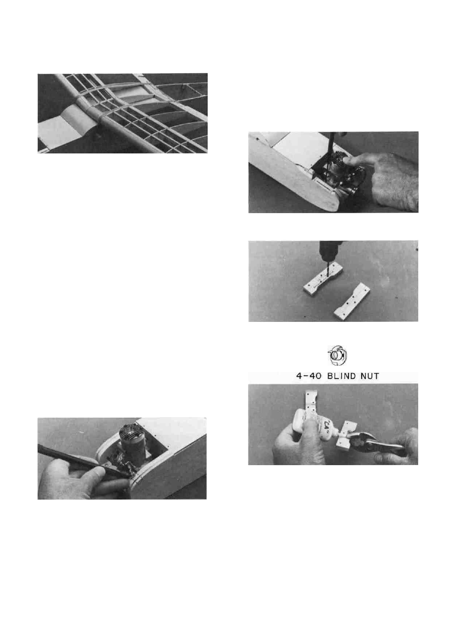
A-Push the blind nut in part way with your
finger.
B- Apply a drop of thick CA around the base
of the nut.
C- Immediately squeeze the nut in, using a
pliers or a vise.
D 6. Drill 1/8" holes through the breakaway plates
at the marked locations.
D 7. Install 4-40 blind nuts in the bottom of the
holes you just drilled, as follows:
23