Great Planes PT-40 Kit (original) User Manual
Page 10
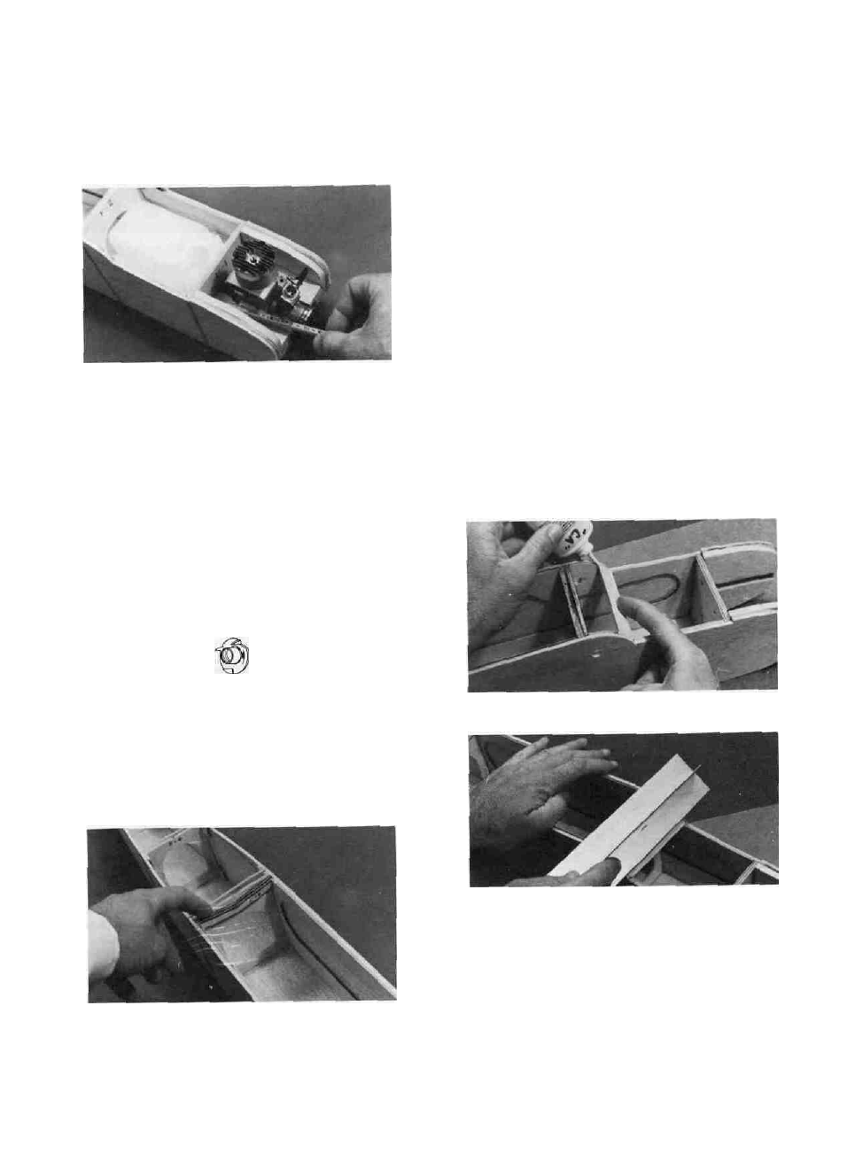
NOTE ON ENGINES: The engine mount
"breakaway plates" have been cut to an average width
which will permit mounting almost any engine you
choose. However, you may have to trim these plates
slightly to fit your engine. The best way to do this is
to sand or file away a little at a time from the inside
edges of both breakaway plates until your engine fits
between the plates.
NOTE ON FUEL TANK: The PT40 requires
any 6 or 8 oz. fuel tank of your choice. Most tanks
have three possible openings, one for fuel pick- up,
and two for the fill/vent lines. We recommend that
you only use two lines. Run one line from the "klunk"
pick-up to the fuel fitting on the engine carburetor
and the other to the "pressure tap" fitting on the
muffler.
D 14. Because you have not yet glued the fuse parts
together, you may now carefully remove F-l and drill
the holes for the fuel lines and throttle pushrod.
D 15. Insert four 4-40 blind nuts part-way into the
1/8" holes previously drilled. Insert them from the
back side of F-l. Apply one drop of thick CA glue
under the wide part of each nut, then immediately
press them firmly in place with a pliers or a vise.
4-40 BLIND NUT
D 16. Replace F-l back into the fuse.
D 17. By now you should have decided which wing
you are going to build, "Wing A" (without ailerons),
or "Wing B" (with ailerons). If you have chosen'
"Wing A", find the four F-2A wing saddles and put
them into the slots behind F-2 and in front of F-3. If
you have chosen "Wing B", use the F-2B saddles.
D 18. Check your assembly of the fuselage, making
sure that all former tabs are in their respective
notches and all parts are in place. Set the fuselage
assembly on the plan top view. Your fuse assembly
should line up with the plan within 1/16". If not,
something is wrong and you should try to straighten
it out. If the alignment is far off and you can't find
the problem, consult with an experienced model buil-
der to correct the problem before proceeding.
D 19. Lay down a 50" long piece of waxed paper to
protect your building surface. Set the fuselage assem-
bly upright (in its normal position) on the waxed
paper. With everything in its proper place, apply thin
CA glue to all the joints, around the formers and
along the bottom. Wait a minute for the glue to set,
then apply thick CA to the joints to make sure a
good bond exists, especially in the joints that do not
fit perfectly. Note: The use of "Zip Kicker" or other
CA glue accelerator will be helpful when using thick
CA to fill any large gaps.
D 20. Remove the rubber bands from the fuselage.
In the above step you may have glued the rubber
bands to the wood in some places. If so, just cut the
rubber away from the wood with an X-Acto knife.
INSTALL THE WINDSHIELD
AND HATCH
D 1. Put the 1/2" balsa triangle windshield brace
in place and apply thin CA glue.
D 2. Sand the 1/2" balsa triangle to match the curve
on the fuse sides.
D 3. Sand the bottom edge of the l/8"balsa
windshield at an angle so it will rest flat on the fuse
sides.
D 4. Apply thick CA to the 1/2" balsa triangle, then
immediately place the windshield in position, hold-
ing the bottom against the triangle.
10 (See photo, top of next page.)