Great Planes Fun One 40 - GPMA0490 User Manual
Page 25
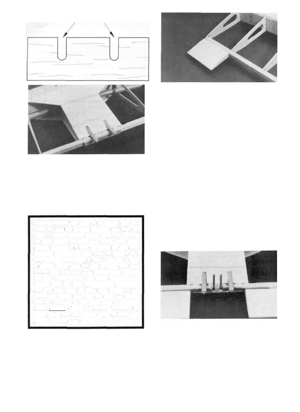
Cut out for dowels
D 3. Cut the front center sheet at an angle to match up
with the rear pieces as shown in the photo. Also cut away
the sheeting on the bottom of the wing for either the servo
cables or the aileron servo whichever the case may be.
that they follow the natural contour of the wing and are
not tilted up or down. Sand them to fair smoothly with
the TE and sand the ends flush with rib W10.
D 6. Tack glue the 1/8" plywood Wing Tips (FUN1W01)
in place with two drops of med. CA. They should line up
with the front portion of the airfoil and be centered with the
3" aileron portion at the TE. Sand the wing and wing tip
to get a smooth transition between the two. Remove the
wing tip and sand both sides smooth and lightly sand the
edges to remove any "fuzz". They will be glued back on
after the plane is covered.
D 4. Sand the leading edge so it will blend in smoothly
with the leading edge sheeting.
IMPORTANT: The shape of the leading edge will
affect the way this airplane performs snap rolls and
spins. A blunt, rounded leading edge will "soften"
the stall, making the plane very docile when flying
slowly, enabling it to flare nose-high for very slow
landings; however, this may cause the plane to be a
little sluggish when trying to enter a snap roll or spin.
A sharper leading edge will help the plane enter snap
roll and spin maneuvers more crisply, while sacrific-
ing only a little of the low speed stability. The
leading edge has been approximately pre-shaped,
and will work great for most sport flying. If you
would like crisper snap rolls and spins you should
sand the inner 1/3 of each wing panel to gradually
form a slightly sharper LE radius. To avoid tip
stalls, make sure the leading edges of both wing
panels have the same shape.
D 5. Cut 3" off each aileron (FUN 110) and glue the
short pieces to the tip end of each trailing edge. Make sure
INSTALL AILERON TORQUE RODS
(One aileron servo only)
D 1. Remove the dowel aligner which was tack glued
into place.
D 2. Cut a groove to fit the torque rods in the TE. A
clearance groove also has to be cut in the top of the TE to
allow the torque rods to move. Also cut small clearance
notches in the dowel aligner. Note: The torque rod
horns must exit the BOTTOM of the wing! Test fit the
torque rods in the groove, they should be totally in the TE
so the dowel aligner will fit back into place.
25