Great Planes Revolver GP/EP ARF 59" - GPMA1018 User Manual
Page 18
18
❏
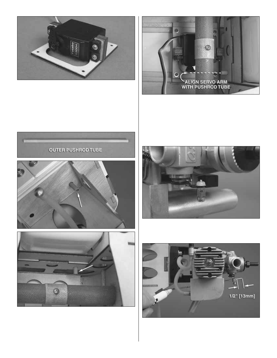
8. Cut three arms from a four-armed servo arm included
with your throttle servo. Enlarge the outer hole of the servo
arm using a 5/64" [2mm] drill bit. Center the servo with your
radio system and install the arm perpendicular to the servo
case. Install the throttle servo onto the throttle servo tray
using the hardware supplied with the servo. Most engine
models will require the throttle servo to be oriented on the
tray in the direction shown.
❏
9. Roughen the ends of the 6" [152mm] outer pushrod
tube using 220-grit sandpaper. Slide the outer pushrod tube
through the hole in the fi rewall that is closest to the engine
carburetor. The tube should also pass through one of the
pushrod tube holes in the second former. Glue the outer
pushrod tube to the fi rewall and second former.
❏
10. Place the throttle servo tray into the fuselage, aligning
the servo arm with the outer pushrod tube. Drill through the
four mounting holes on the tray using a 1/16" [1.6mm] bit.
Thread a #2 x 3/8" [9.5mm] self-tapping screw into each hole
and back it out. Apply a couple drops of thin CA glue to each
hole to harden the wood. When the CA has dried, screw
the tray to the fuse using four #2 x 3/8" [9mm] self-tapping
screws and four #2 fl at washers.
❏
11. Install a brass screw-lock connector onto the outer hole of
the throttle arm on the carburetor using a nylon retainer. Thread a
4-40 x 1/8" [3mm] SHCS loosely into the screw-lock connector.
❏
12. To make the remaining 2-56 x 36" [914mm] pushrod
easier to work with, cut it down to approximately 18" [457mm].
The threaded end will not be used so it can be cut off. Slide
the pushrod through the outer pushrod tube installed in the