Install the power system glow engine installation – Great Planes Revolver GP/EP ARF 59" - GPMA1018 User Manual
Page 16
16
INSTALL THE POWER SYSTEM
Glow Engine Installation
The Revolver ARF is designed to be fl own with a .46-.55 two-
stroke glow engine, .70 four-stroke glow engine, or an out-
runner brushless motor. If you plan to install a brushless motor,
skip ahead to page 19, "Brushless Motor Installation".
❏
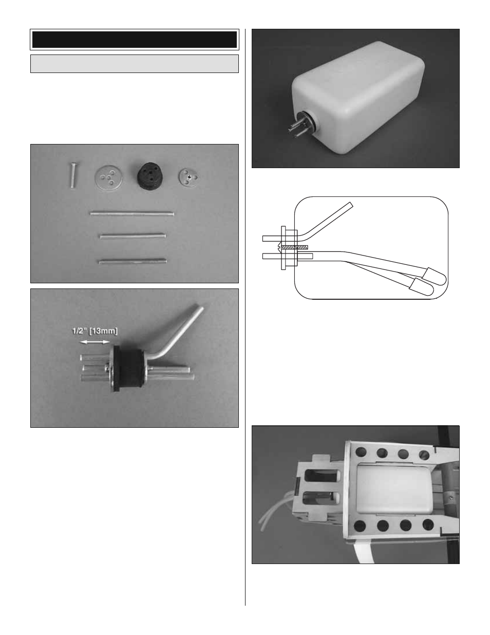
1. The fuel tank can be assembled as a two line system
consisting of a vent (pressure) line to the muffl er and a
carb line. Filling and emptying of the tank would need to be
done through the carb line, or an optional fuel fi ll valve (not
included). The tank can also be assembled as a three line
system having a vent line, carb line, and fi ll line. If installing
a fi ll line, puncture the top of the stopper above the sealed
off fuel tube hole. The fi ll and carb lines should extend out
1/2" [13mm] beyond the stopper and the vent line should
be bent upwards and left uncut. With the tubes installed in
the stopper, fi t the stopper plates loosely in place with the
3x25mm phillips screw to hold the assembly together.
TOP OF TANK
VENT
FILL AND CARB LINES
❏
2. Fit the stopper assembly into the tank with the vent
line pointing toward the top of the tank, but not touching.
The fuel tubing and clunks (fuel pickup) on the carb and fi ll
lines should almost reach the back of the tank but not touch.
The clunks must be able to move freely inside the tank when
assembled. Adjust the length of the fuel tubing accordingly.
When satisfi ed, tighten the 3x25mm screw in the stopper to
secure it in place (do not over-tighten). Mark the side of the
tank that must face up when installed in the plane. We also
suggest marking the tubes in the stopper.
❏
3. Attach a 6"-7" [152mm-178mm] piece of fuel tubing
onto each line coming from the tank. Insert the tank into the
fuselage with the correct side facing up. The fuel tubing should
be routed through the hole in the center of the fi rewall.
16