Install the tail servos & pushrods – Great Planes Revolver GP/EP ARF 59" - GPMA1018 User Manual
Page 13
13
elevator halves. Mark the locations of the control horn mounting
holes onto the elevator halves and drill 1/16" [1.6mm] holes at
the marks. Do not drill all the way through the elevator halves!
Thread a #2 x 3/8" [9.5mm] self-tapping screw into each hole
and back it out. Apply a couple drops of thin CA glue to each
hole and let it harden. Attach the elevator control horns to the
elevators using four #2 x 3/8" [9.5mm] self-tapping screws.
❏
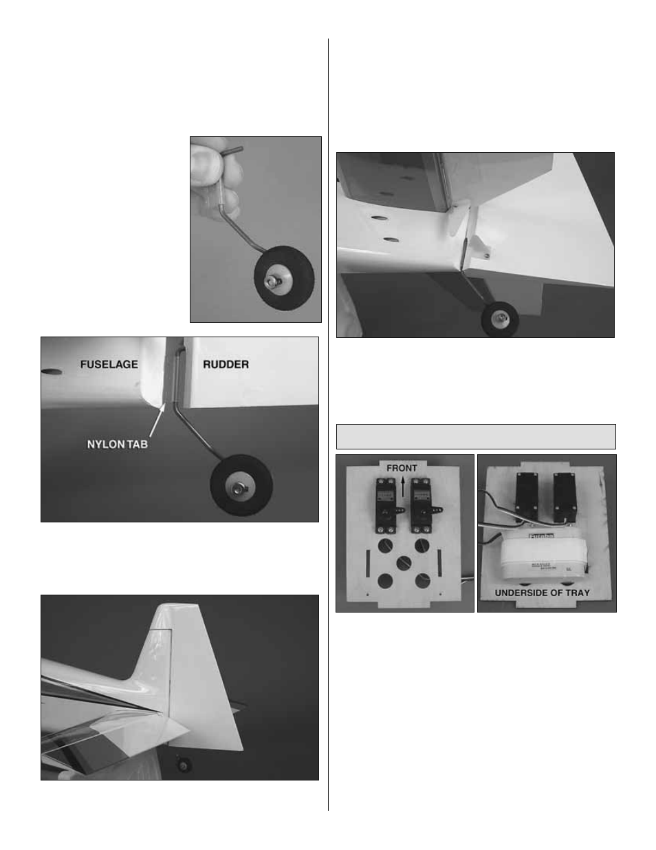
6. Secure the tail wheel to
the tail wheel assembly with a
3/32" [2.4mm] wheel collar and a
4-40 set screw. Be sure that the
tail wheel rotates freely on the
axle. Oil the axle if necessary.
❏
7. Test fi t the rudder to the fuselage with the tail wheel
assembly installed in the orientation shown. Make any
adjustments necessary so the nylon tab on the tail wheel
wire fi ts all the way into the slot in the fuse.
❏
8. Roughen the portion of the tail wheel assembly that fi ts
into the rudder with 220-grit sand paper and clean it off with
alcohol. Glue the tail wheel wire into the hole in the LE of the
rudder with medium or thick CA glue. Be sure not to get glue
onto the nylon tab where it rotates on the wire (oil applied
on the tail wheel wire around the tab will help prevent glue
from sticking to it). Lightly coat both sides of the nylon tab
with thick CA glue or epoxy and fi t the rudder to the fuselage
along with two CA hinges. Glue the CA hinges in place with
thin CA glue.
❏
9. As you did with the elevator halves, use a 2-56 x 36"
[914mm] pushrod to position a control horn onto the left side
of the rudder. Attach it using two #2 x 3/8" [9.5mm] self-
tapping screws.
Install the Tail Servos & Pushrods
❏
1. Install the elevator and rudder servos into the servo tray
in the direction shown using the hardware supplied with the
servos. Be sure to harden the screw holes with thin CA as was
done with the aileron servos. Cut three arms from two four-
armed servo arms. Center the servos with your radio system
and install them onto the servos with the servo screws. Enlarge
the outer holes of each servo arm with a 5/64" [2mm] drill bit.
If you plan to install a brushless motor, an aft receiver battery
location is provided on the servo tray for balancing purposes.
Use the included hook and loop material with a piece of 1/4"
[6mm] or 1/2" [13mm] foam rubber (not included) to strap the
receiver pack to the underside of the servo tray so it will not
interfere with the elevator and rudder pushrods. If you are
installing a glow engine, the receiver battery is installed at the
front of the fuselage later on in the build process.