Mount the tail wheel, bracket and support wires – Great Planes Giant Citabria 30cc/EP ARF - GPMA1435 User Manual
Page 14
14
❏
9. Just like the elevator there is a plywood plate at the
bottom of the rudder. Install the clevis into the second hole
from the bottom of a control horn. Slide the 4-40 wire into the
hole in the side of the fuselage and the place the control horn
onto the plywood plate. The holes in the control horn should
be aligned over the hinge line.
❏
10. Once the horn is properly positioned mark the location
of the control horn mounting holes onto the rudder with a felt
tip marker. On each of the marks drill a 3/32" [2.4mm] hole
through the plywood plate. Do not drill through the top of
the rudder!
❏
11. Install and then remove a #4 x 3/8" sheet metal screw
into each of the holes. Apply a drop of thin CA glue into each of
the holes to harden the threads. Once the glue has hardened
secure the control horn to the elevator with the four screws.
❏
12. Install the grommets and eyelets on to a servo. Cut
three arms from a four arm servo horn, center the servo and
install the horn onto the servo. Install a 4-40 solder clevis into
the outer hole in each of the servo arms. Place the servo in
the servo tray with the servo arms aligned with the pushrod
wire. Drill a 1/16" [1.6mm] hole through each of the mounting
holes in the two servos. Install and remove a servo mounting
screw into each of the holes you drilled. Apply a drop of thin
CA glue to harden the threads. When the glue has hardened
secure the servo with the screws.
❏
13. Center the rudder and the rudder servo arm. Using the
solder clevis as your guide, make a mark on the pushrod wire
where it needs to be cut. Remove the clevis from the rudder
control horn and remove the pushrod from the fuselage. Cut
the wire on the mark you made. Solder a 4-40 solder clevis
to the wire using the same procedure used on the elevators.
When the solder has cooled remove the threaded clevis
and 4-40 nut from the threaded end of the wires. Slide a
silicone clevis keeper onto the solder clevis. Re-install the
wire through the front of the fuselage into the pushrod guide
tubes. Attach the clevis from each pushrod wire to the outer
hole of the servo arm. Re-install the nut and threaded clevis
onto the wire, adjusting it so that the rudder is centered. Then
secure the rudder with the clevis.
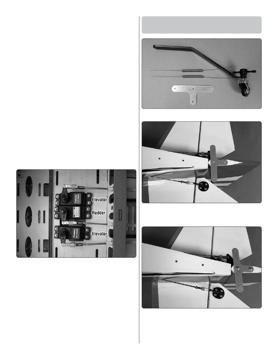
Mount the Tail Wheel, Bracket
and Support Wires
❏
1. Locate all of the components of the tail wheel assembly.
❏
2. Place the aluminum “T” bracket on the bottom of the
rudder. Mark the location of the mounting holes with a felt tip
marker onto the bottom of the rudder.
❏
3. Drill a 3/32" [2.4mm] hole into the rudder on each of
the marks. Insert and then remove a #4 x 3/8" [9.5mm] sheet
metal screw into each of the holes you drilled. Apply a drop
of thin CA glue into each of the holes to harden the threads.
Once the glue hardens secure the “T” bracket to the rudder
with two #4 x 3/8" [9.5mm] screws.