Set the control throws – Great Planes Cirrus SR22 .46-55 ARF - GPMA1363 User Manual
Page 26
26
Set the Control Throws
To ensure a successful fi rst fl ight, set up your Cirrus SR22
ARF according to the control throws specifi ed in this
manual. The throws have been determined through actual
fl ight testing and accurate record-keeping, allowing the
model to perform in the manner in which it was intended. If,
after you have become accustomed to the way the Cirrus
SR22 ARF fl ies, you would like to change the throws to
suit your taste, that is fi ne. However, too much control
throw could make the model too responsive and diffi cult to
control, so remember, “more is not always better.”
❏
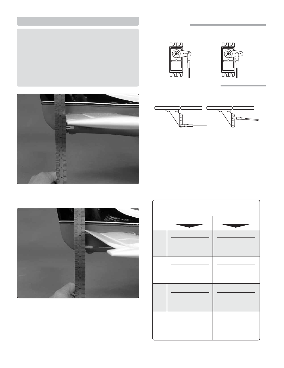
1. Hold a ruler vertically on your workbench against the
widest part (front to back) of the trailing edge of the elevator.
Note the measurement on the ruler.
❏
2. Measure the high rate elevator throw fi rst. Move the
elevator up with your transmitter and move the ruler forward
so it will remain contacting the trailing edge. The distance
the elevator moves up from center is the “up” elevator throw.
Measure the down elevator throw the same way.
The pushrod farther out
means More Throw
The pushrod closer in
means Less Throw
The pushrod farther out
means Less Throw
The pushrod closer in
means More Throw
At the Servos
At the Control Surfaces
❏
3. If necessary, adjust the location of the pushrod on the
servo arm or on the elevator horn, or program the ATVs in
your transmitter to increase or decrease the throw according
to the measurements in the control throws chart.
❏
4. Measure and set the low rate elevator throws and the
high and low rate throws for the rest of the control surfaces
the same way. If your radio does not have dual rates, we
recommend setting the throws at the high rate settings.
NOTE: The throws are measured at the widest part of the
elevators, rudder and ailerons.
These are the recommended
control surface throws:
ELEV
A
T
OR
HIGH RATE
LOW RATE
7/16"
[11mm]
17°
Up
7/16"
[11mm]
17°
Down
5/16"
[8mm]
12°
Up
5/16"
[8mm]
12°
Down
3/4"
[19mm]
21°
Up
3/4"
[19mm]
21°
Down
5/8"
[16mm]
17°
Up
5/8"
[16mm]
17°
Down
1-1/2"
[38mm]
35°
Down
1"
[25mm]
30°
Right
1"
[25mm]
30°
Left
5/8"
[16mm]
18°
Right
5/8"
[16mm]
18°
Left
R
UDDER
AILER
ONS
FLAPS