Cabletron Systems 2E48-27R User Manual
Page 35
Connecting to the Network
2E48-27R/2E49-27R User’s Guide
3-11
An FE-100TX installed in port slot 25 and/or 26 has an internal crossover
switch. When connecting a workstation, use a straight-through cable and
set the Fast Ethernet Interface Module crossover switch shown in
to the crossed over position marked with X. When connecting
networking devices, such as another bridge, repeater, or router, use a
straight-through cable and set the Fast Ethernet Interface Module
crossover switch shown in
to the not crossed over position,
marked with =.
Figure 3-7
FE-100TX Crossover Switch
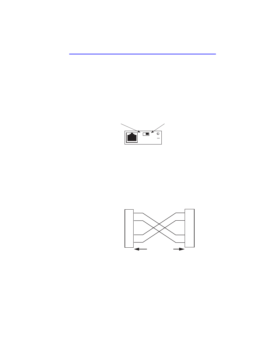
A schematic of a crossover cable is shown in
. If the wires do
not cross over, use the switch on the FE-100TX to internally cross over
the RJ45 port.
shows how to properly set the FE-100TX
crossover switch.
Figure 3-8
Schematic of Crossover Cable
Connect an FE-100TX to a twisted pair segment as follows:
1.
Ensure that the device connected to the other end of the segment is
powered ON.
Position X
(crossed over)
1. RX+
2. RX-
3. TX+
4. NC
5. NC
6. TX-
7. NC
8. NC
Position =
(not crossed over)
1. TX+
2. TX-
3. RX+
4. NC
5. NC
6. RX-
7. NC
8. NC
FE-100TX
10
16651_05
100
=
x
TX+
TX–
RX+
RX–
2
1
3
6
TO
10BASE-T Device Port
TX+
TX–
2
1
3
6
NOTE:
RX+/RX– and TX+/TX–
must share a common
color pair.
TO
RJ45 Port
2251-31
RJ45 to RJ45
RX+
RX–