Garelick 71092 MOTOR BRACKET User Manual
Page 3
Installation Instructions for
Auxilliary Hydraulic Outboard Motor Bracket
Form 12.575
Write for
a Complete
Catalog
644 2nd Street, PO Box 8
St. Paul Park, Minnesota 55071
Phone: 651-459-9795
E-mail: [email protected]
Website: www. garelick.com
04/06
Model No: 71092
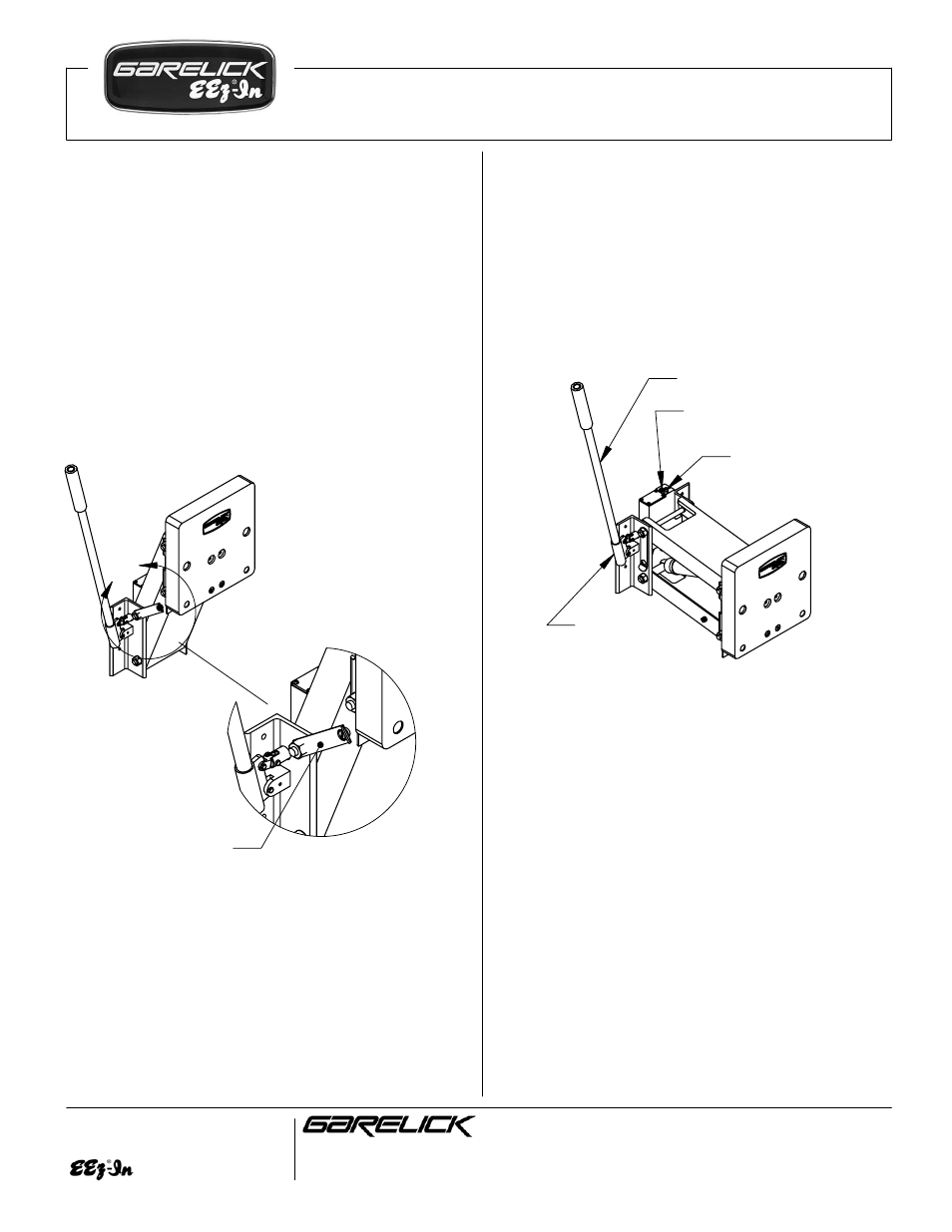
Raising Auxiliary Outboard Motor:
Step 1: Place slotted end of pump handle over the
relief valve and turn clockwise until tight (valve is
now closed).
Step2: Place pump handle into handle socket and
pump in a starboard-to-port manor.
Step 3: When the motor bracket is not in use it is
recommended that the safety locking strap be
used. Raise the motor bracket to the highest
position. Swing the safety strap so that it captures
the pin located on the u-channel as shown below.
Operation Instructions:
NOTE: The motor bracket is equipped with a load
limiting device (Fig 4) for safety reasons. As the
unit reaches it's maximum height you will feel
resistance against the handle as the pressure
relief valve operates. At this point please stop
pumping as the unit is unable to raise any further.
Maintenance Instructions:
Lowering Auxiliary Outboard Motor:
Step 1: Place slotted end of pump handle over the
relief valve and SLOWLY turn counter-clockwise
until motor starts to lower (valve is now open).
Step2: Once motor is at desired height turn the
relief valve clockwise until tight (valve is closed).
Release Valve
Handle
Handle
Socket
Lubrication:
To minimize wear, keep all pivot points well
lubricated with a medium to heavy lubricating
oil/grease (marine grade).
Washing:
In a salt water environment, it is recommended
that the bracket is periodically washed with soap
and fresh water and waxed with a good marine
grade polish/wax.
Adding oil:
The cylinder and valve block are filled with
hydraulic oil and are self-contained, however,
if the motor bracket does not raise to full height it
may be low on hydraulic oil. To add oil, the
bracket MUST be raised to it's maximum height
position and secured with the safety strap. Once
the bracket is secured remove the 4 screws,
Figure 4
Load Limiting Device
(DO NOT ADJUST)
DETAIL A
Figure 3
A
Safety Lock