Garelick 71039 MOTOR BRACKET User Manual
Garelick Accessories for water
Mounting and Operating Instructions for
Outboard Motor Bracket
Models 71033, 71056, and 71039
Form 12.185
IMPORTANT INSTRUCTIONS
1. Read instructions completely before starting assembly.
2. Motor bracket must remain in “UP” position throughout
installation.
3. DO NOT operate motor bracket unless motor is installed
on bracket.
4. NOTE: This bracket is under spring tension. Exercise
extreme caution when adjusting and installing.
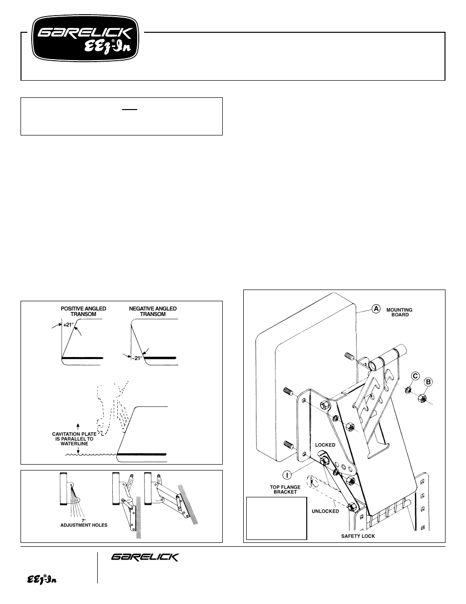
BRACKET ANGLE ADJUSTMENT INSTRUCTIONS
Refer to Fig. 1.
Measure the exact angle and direction of the transom on your
boat. Determine if your motor can be adjusted so the cavitation
plate is parallel to the waterline. If this is possible then skip the
following adjustment instructions (Figs. 2-7) and go to the
“Mounting Instructions” on Page 3. If your motor cannot be
trimmed properly, then follow the section below for the type of
transom you have: “POSITIVE” or “NEGATIVE.”
FIG. 1
FIG. 2
FIG. 3
Write for
a Complete
Catalog
Phone: 651-459-9795
PO Box 8, 644 2nd Street
E-mail: [email protected]
St. Paul Park, Minnesota 55071
On the Web: www.garelick.com
10/08
FOR NEGATIVE ANGLED TRANSOMS
Refer to Fig. 2, 3 & 4
Now that the angle and direction of your transom have been
determined, choose the adjustment hole on your bracket that
will best compensate for the angle of your transom.
NOTE: Each adjustment hole represents a 7° increment.
Refer to Figs. 3 & 4
Adjust your bracket by removing mounting board (A). This is
done by unscrewing four nuts (B) and lockwashers (C). Pull
safety lock out and rotate it to the “unlocked” position. Unscrew
locknut (D) and pull out pivot bolt (E). Now replace pivot bolt
(E) through the desired adjustment hole in the top flange
bracket (I). Reassemble unit by sliding bolt through washer (F)
lower lever arm hole, spacer (G), lock bar arm hole spacer (H),
lock bar arm hole, spacer (G), lower lever arm hole, washer (F)
and out the other desired adjustment hole.
Secure bolt in position with nut (D); do not overtighten nut so as
to bind operation of bracket. NOTE: Bolt must protrude through
the top of the nut to insure locking. Pull safety lock out and
rotate it back into the “locked” position. Replace the mounting
board (A) on your bracket with washers (C) and nuts (B).
Secure in position. Refer to mounting instructions.
This bracket is
NOT for use
with 4-stroke
outboard motors.
NOTE: Vertical travel distance assumes a transom 90° to the water surface.
If the angle is greater than 90° we recommend
using a wedged shim to bring the
angle back to 90° to maintain
travel distance and proper
cavitation plate position for
best performance.
Transom Mounting Hardware NOT Supplied Due to Various
Transom Thicknesses.
Recommend 5/16" Stainless Steel Fasteners