Garelick 71091 MOTOR BRACKET User Manual
Garelick Accessories for water
Mounting and Operating Instructions for
Heavy Duty Outboard Motor Bracket
Models 71090 and 71091
Form 12.295
OUTBOARD MOTOR BRACKET MOUNTING INSTRUCTIONS
Transom Mounting Hardware NOT Supplied Due to Various
Transom Thicknesses.
Recommend 5/16" Stainless Steel Fasteners
1. Read instructions completely before starting assembly.
2. Motor bracket must remain in “UP” position throughout
installation.
3. DO NOT operate motor bracket unless motor is installed
on bracket and is attached to the boat.
4. This bracket is under spring tension. Exercise extreme
caution when adjusting and installing.
MOUNTING INSTRUCTIONS
Refer to Fig. 1
Measure the distance on your outboard motor between the
cavitation plate and the upper inside edge of the mounting
clamp. Subtract 2" from this length. Then add the total travel
distance of your model outboard motor bracket from the table
below to the distance measured on your motor.
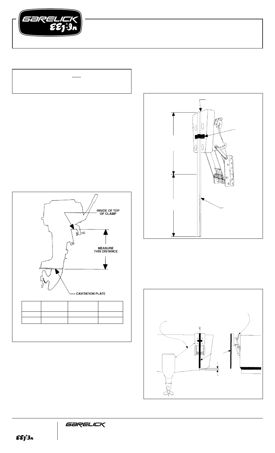
Refer to Fig. 2
Mark this total length on a stick and tape it so that the top is
flush with the top of the mounting board of the motor bracket.
Choose the most appropriate side of your transom for mounting
the bracket. Position your bracket so it will not interfere with the
turning operation of your main motor or rudder.
Refer to Fig. 3
For Powerboat Installation:
Take your outboard motor bracket
with the stick taped on and place the mounting flanges on your
transom. Position the bracket so the bottom of the stick is one
inch above the boat’s bottom at the centerline of the outboard
motor bracket.
FIG. 3
Write for
a Complete
Catalog
Phone: 651-459-9795
PO Box 8, 644 2nd Street
E-mail: [email protected]
St. Paul Park, Minnesota 55071
On the Web: www.garelick.com
10-08
FIG. 1
MOTOR
WEIGHT NOT
VERTICAL
MODEL
H.P. RATING
TO EXCEED
TRAVEL
71090
7
1
⁄
2
TO 30
169 LBS.
9
1
⁄
2
"
71091
7
1
⁄
2
TO 25
175 LBS.
15
1
⁄
2
"
FIG. 2
DISTANCE FROM CLAMP
TO CAVITATION PLATE
LESS 2"
TRAVEL DISTANCE
FROM TABLE
TAPE
STICK
TOP OF STICK IS EVEN WITH
TOP OF MOUNTING BOARD
IF THE BRACKET RELEASE HANDLE IS AT OR
BELOW THE RUB RAIL OR THE TOP OF THE
TRANSOM, ADD A 1" SHIM OF SUITABLE MATERIAL
BETWEEN THE TRANSOM AND THE BRACKET TO
ALLOW FULL AFT MOTION OF RELEASE HANDLE.
BRACKET AND MOTOR DO NOT INTERFERE WITH
OPERATION OF MAIN MOTOR UNIT.
STICK
1"
BRACKET IS POSITIONED SO THE BOTTOM OF THE
STICK IS 1" ABOVE THE BOAT’S BOTTOM AT THE
CENTERLINE OF THE MOTOR BRACKET
(over)
NOTE:
Vertical travel is based on installation that is
perpendicular to waterline.
Transom Mounting Hardware NOT Supplied Due to Various
Transom Thicknesses.
Recommend 5/16" Stainless Steel Fasteners