Garelick 71039 MOTOR BRACKET User Manual
Page 4
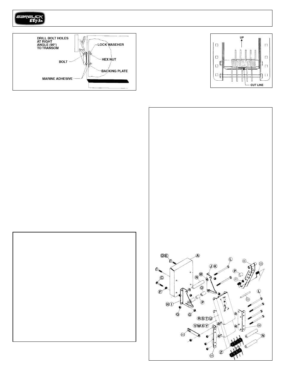
Refer to Fig. 13
If your transom is less than 2" thick, it is recommended that a
backing plate be made and mounted on the inside of the
transom for needed rigidity. Attach your motor bracket to the
transom by coating the inside surfaces of the mounting flanges
and backing plate with a marine adhesive/sealant compound
and then squeeze a small amount into each bolt hole on both
sides of the transom. Secure the bracket to the transom as
illustrated in Fig. 13. The bracket is now ready for motor
mounting.
OPERATING INSTRUCTIONS
To Lower Motor:
Disengage safety lock by pulling it out and
rotating it away from the locknut. Pull lever handle towards the
boat to disengage locking pin. Grasp motor and SLOWLY
lower it to desired height. Release lever handle; locking pin will
snap forward into slot.
To Raise Motor:
Pull lever handle towards the boat to disengage
locking pin. Grasp motor and lift up to desired height. Release
lever handle; locking pin will snap forward into slot. Engage
safety lock by pulling it out and rotating it so it snaps over the
pivot bolt.
AUXILIARY OUTBOARD MOTOR BRACKET
IMPORTANT CAUTION GUIDELINES
1. Install motor bracket only in “up” position with safety
lock in “locked” position.
2. Always remove your motor from the bracket when
trailering. Failure to do so could result in damage to
boat, motor and bracket.
3. Do not exceed the stated H.P. rating or weight.
4. Use a safety cable when operating your motor.
5. Operate motor at low speed.
6. Avoid turning motor at full throttle, refrain from sharp
turns.
7. Operate motor in lowest position possible for best
performance.
8. Always raise and tilt motor when not in use.
9. Keep pivoting bolts greased to insure smooth
operation.
SPECIAL NOTE:
The bracket
springs counter most of the
motor’s weight; however, a
slight push or lift may be
needed. If “lowering” the
bracket is too difficult due to
the use of a “light” motor, it
may then be desirable to
decrease some spring
tension. This is accomplished
by cutting one but not more
than three springs as illustrated in Fig. 14. Cut one spring at a
time and test operation before cutting another. Make sure to cut
the spring’s leg as close to the coil as illustrated.
PARTS LIST
ITEM
MODEL NO.
PART NO.
DESCRIPTION
QTY.
A
71033,7,8,9,56
06.283
Mounting Board
1 Ea
C
71033,7,8,9,56
03.244
5/16-18x2 1/2 SS Carrbolt
2 Ea
D
71033,8,9,56
03.158
5/16-18x2 1/2 SS PB
2 Ea
E
71037
03.141
5/16-18x2 5/16 SS PB
2 Ea
F
71033,7,8,9,56
03.030
SS Pronged Washer
2 Ea
G
71033,7.8,9,56
03.166
5/16-18 HX SS 1W Locknut
4 Ea
H
71037,8,9,56
57.051
71037 Short Angle Right
1 Ea
I
71033
57.077
71033 Short Angle Right
1 Ea
J
71037,8,9,56
57,050
71037 Short Angle Left
1 Ea
K
71033
57.076
71033 Short Angle Left
1 Ea
L
71033,7,8,9,56
03.250
3/8-16x5 3/4" HH SS CS
6 Ea
M
71033,7,8,9,56
03.252
1x25/64x.030 PP Washer
8 Ea
N
71033.7,8,9,56
06.109
Plastic Spacer 4.&80
3 Ea
O
71033,7,8,9,56
06.107
Plastic Spacer 1.609
2 Ea
P
71033,7,8,9,56
06.108
Plastic Spacer 1.375
2 Ea
Q
71033,7,8,9,56
03.028
3/6-16 HX SS 1W Locknut
6 Ea
R
71033
57.079
71033 Top Plate Welded
1 Ea
S
71037
57.054
71037 Top Plate
1 Ea
T
71038,56
57.056
71038 Top Plate
1 Ea
U
71039
57.058
71039 Top Plate
1 Ea
V
71033
57.081
71033 Bottom Plate Welded
1 Ea
W
71037
57.055
71037 Bottom Plate
1 Ea
X
71038,56
57.057
71038 Bottom Plate
1 Ea
Y
71039
57.059
71039 Bottom Plate
1 Ea
Z
71033,7.8,9,56 49.154
Torsion
Spring
(SS-71037)
4-10
AA
71033,7,8,9,56
57.052
71037 Long Angle Left
1 Ea
BB
71033,7,8,9,56
57.053
71037 Long Angle Right
1 Ea
CC
71033,7,8,9,56
57.061
71037 Red 5/16"x4 1/2"
1 Ea
DD
71033,7,8,9,56
49.153
Double Torsion Spring
1 Ea
EE
71033,7,8,9,56
03.253
C17022-SS-010 Lock Washer
1 Ea
GG
71033,7,8,56 57.083
Safety
Latch
HH
71039
57.084
Safety Latch
71033,7,8,9,56
57.063
71037, 8,9 Hardware Pack
1 Ea
71033,7,8,9,56
12.041
SS OBMB Label #1
1 Ea
71037
12.042
SS OBMB Label #2
1 Ea
71033,7,8,9,56
12.062
SS Care Maint Label
1 Ea
71033,7,8,9,56
12.066
SS OBMB Caution Label
1 Ea
71033,8,56
07.276
Ctn 8 1/2”x8”x20”
1 Ea
71037
07.275
Ctn 8"x6 3/4"x19 3/8"
1 Ea
71039
07.277
Ctn 8 1/2"x8 1/2"x 22 1/4"
1 Ea
Mounting and Operating Instructions – Outboard Motor Bracket
Form 12.185
FIG. 13
FIG. 14