Garelick 71039 MOTOR BRACKET User Manual
Page 2
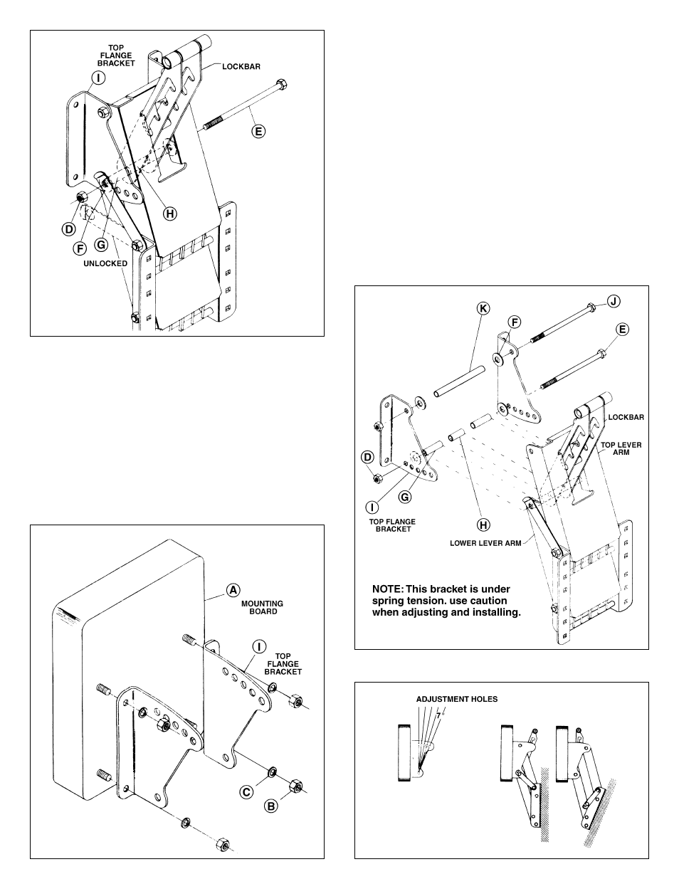
FOR POSITIVE ANGLED TRANSOMS
Refer to Figs. 5, 6 & 7
Begin the adjustment of your bracket by removing mounting
board (A). This is done by unscrewing four nuts (B) and
lockwashers (C). Pull safety lock out and rotate it to the
“unlocked” position. Unscrew locknut (D) and pull out pivot bolt
(E). Unscrew locknut (L) and pull out pivot bolt (J). Now flip the
top flange brackets over and put the left bracket on the right
side and the right on the left side as illustrated in Fig. 5 insert.
Reattach the flange brackets to the bracket by sliding pivot bolt
(E) through the lower hole in the flange bracket, (I), washer (F)
lower lever arm hole, spacer (G), lockbar arm hole, spacer (H),
lock bar arm hole, spacer (G) lower lever arm hole, washer (F)
and out the other lower hole in the flange bracket. Secure bolt
in position with nut (D); Do not overtighten nut so as to bind
operation of bracket. NOTE: Bolt must protrude through the top
of the nut to insure locking.
Use the measured angle of your transom to choose the proper
adjustment hole in your bracket that will best compensate for
this angle. NOTE: Each adjustment hole represents a 7°
increment (Refer to Fig. 7). Now, replace pivot bolt (J) through
the desired adjustment hole in the top flange bracket (I).
Reassemble unit by sliding bolt through washer (F), upper lever
arm hole, spacer (K), upper lever arm hole, washer (F) and out
other desired adjustment hole in top flange bracket. Secure bolt
in position with nut (L). Now replace the mounting board (A) as
pictured in Fig. 5 on your bracket with washers (C) and nuts (B).
Secure in position. Move safety lock back into “locked”
position. Refer to mounting instructions.
FIG. 4
FIG. 6
FIG. 7
FIG. 5