Snap roll switch (timer is optional), Programmable mixing and examples, Adjustments and flight techniques – Futaba 8SSAP User Manual
Page 34
ADJUSTMENTS AND FLIGHT TECHNIQUES
•SNAP ROLL SWITCH (TIMER IS OPTIONAL)
•When this function is used, snap rolls can be
performed by pushing the Snap Switch 13 . Snap
roll directions can be set using Control Switches
34 and 35 .
1 Set Safety Switch [29] on the trimmer panel to
ACT. Monitor Lamp (D) will blink.
2 A snap roll in the direction set by switches 34
and 35 can now be performed by pushing Con-
trol Switch 13 to ON. The aircraft will con-
tinue to roll as long as the switch is held ON
unless the optional timer function is installed.
3 The optional timer function can be used to
automatically stop the snap roll. Trimmers
[25], [26], [27]. and [28] can be used to set the
time in each direction. The time can be varied
from 0.2 to 2 seconds.
NOTE: The Snap Switch 13 is positioned so
that it is easy to reach. When the snap
roll function is activated, you must
use great care not to push the switch
inadvertently. When the snap roll
function is not desired, always set
Safety Switch [29] to INHIB.
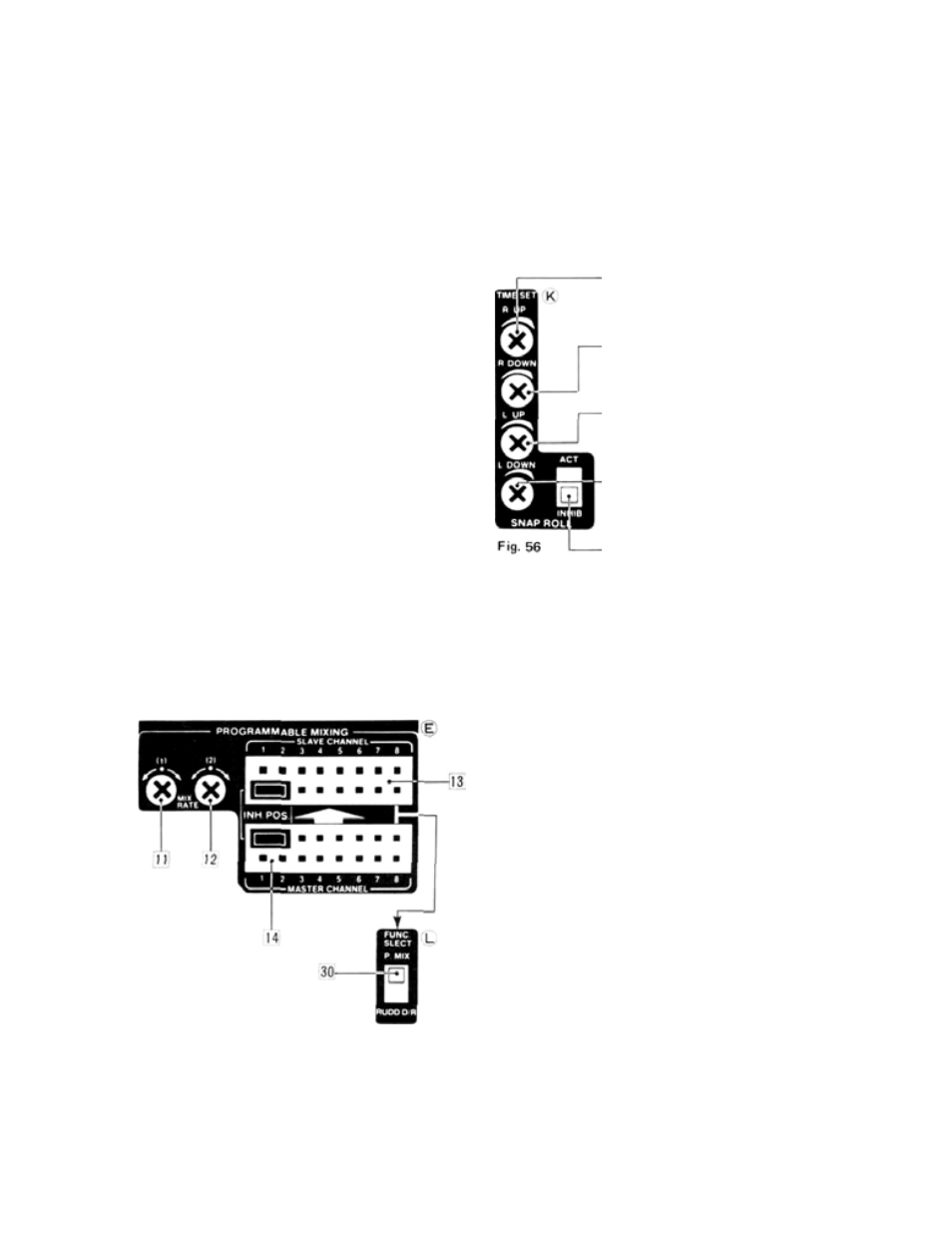
SNAP ROLL TIMER (OPTION)
These are the snap roll time setting
trimmers and snap roll function
safety switches.
2 5 Right up snap roll time set-
ting trimmer for button 34 .
The snap roll time is settable
from 0.2 to 2 seconds.
26 Right down snap roll time
setting trimmer for button
35 . The snap roll time is set-
table from 0.2 to 2 seconds.
[27] Left up snap roll time setting
trimmer for button 36 . The
snap roll time is settable from
0.2 to 2 seconds.
28 Left down snap roll time set-
ting trimmer for button 37 .
The snap roll time is settable
from 0.2 to 2 seconds.
Snap roll function safety
switch.
32
•PROGRAMMABLE MIXING AND EXAMPLES
Fig. 57
•
Programmable mixing of any two channels
desired is possible using the mixing board on the
trimmer panel. Programmable mixing is NOT a
memory function and all programmed mixing
is of the unidirectional type.
•The Master and Slave channels can be desig-
nated using Jumper Connectors 13 and 14 . The
mixing amount in each direction of servo move-
ment is adjustable using Trimmers 11 and 12 .
•When Programmed Mixing is not in use. Con-
nectors 13 and 14 should be placed in the
INHIB position as shown in Fig. 57.
•When Function Select Switch 30 is set to P.
MIX, programmed mixing can be switched ON
and OFF in fhght using Control Switch (16).
When Switch 30 is set to RUDD D/R, program-
med mixing will remain ON if activated using
Connectors 13 and 1 4 , and Control Switch 16)
can be used to turn the Rudder Dual Rate func-
tion ON and OFF.