Introduction and block diagrams, Application range, Block diagrams – Flintec II PC-BASED User Manual
Page 5
FlintWeigh Technical Manual, Rev. 3.03 November 2011
Page 5 of 32
3.
Introduction and Block Diagrams
The W&M approved type FW-01 Scale Interface is the key component to integrate a Weighing System into your
PC. FlintWeigh does not require any separate weight display and the scale interface assures, that the weight
data will be reliably processed in the PC.
It is possible to connect up to 2 scales (up to 16x type RC3D digital load cells respective 2x type LDU digital
amplifiers) via RS485 to the scale interface, which will be connected to the PC via USB interface.
When the scales are based on standard load cells you can select among several LDU types which may be
plugged into socket within the KAL-4 junction box. The selection of the applied LDU will be defined by the
requirements for the weighing application. The technical characteristics of the LDU types and connection
details about digital and standard load cells you can find in chapter 4.
3.1. Application Range
For protecting the consumers all scales which are used for commercial transactions (legal for trade
applications) have to be calibrated in a standardized way. Typical legal for trade scales are retail scales in
shops. Privately used bathroom scales or kitchen scales are examples for scales which don’t require an
approved calibration.
Legal for trade applications
The weighing terminal has an EC type approval which covers standard load cells and scales of the accuracy
class
and
.
All load cells have to keep the tolerances according "OIML R60, Metrological regulation for load cells, Edition
2000".
For selecting the proper weighing module in legal for trade applications, it is required to verify the compatibility
of modules for the weighing instrument (see file KOMPMODENG.XLS on the Flintec CD-ROM).
For further information about software, alibi memory and legal for trade applications see chapter 4.
Industrial applications
All scale connections in industrial applications fall within the responsibility of the scale operator. In such
applications an approved alibi memory is not available.
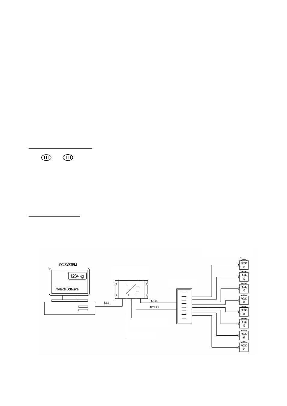
3.2. Block Diagrams
Fig. 3.1: Connection of RC3D digital load cells via KPFD-8 junction box
Digital Load Cells
KPFD-8
Type FW-01
Scale Interface
Alibi memory
Digital I/O
12 V DC Supply