Caution, Important – Fleet Engineers INS-97005 User Manual
Page 2
CAUTION!
The vertical track assembly may be raised a maximum of 1/2”
off the sill. Keep both vertical tracks the same length and same
distance off sill.
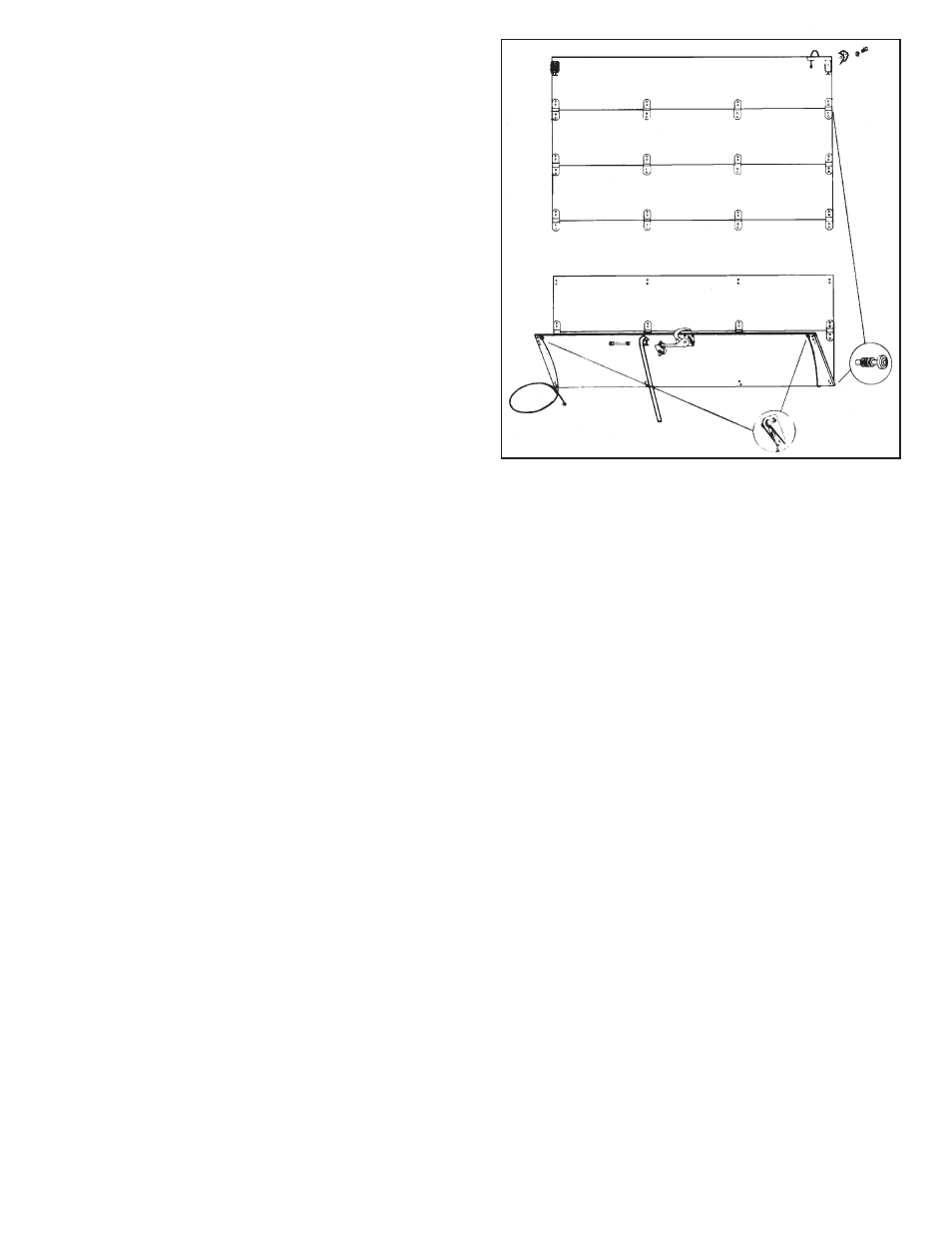
Mount the vertical track mounting angle flush with the inside edge
of the rear corner posts all the way up and down,
Figure 3.
It is critical that the vertical track is installed square. Check the
opening measurements at several points between the vertical
tracks, then measure diagonally. If your measurements are equal,
the door track is square.
The vertical track is to be welded through the plug weld holes to
the post on 12” to 15” centerline. The upper brackets (counterbal-
ance) must be properly secured, welded or bolted, to the header,
Figure 5.
STEP 6: Horizontal Track Installation -
It is important to maintain the same distance between the hori-
zontal and vertical tracks. If wider than the vertical tracks, shim
horizontal track accordingly.
Fasten horizontal tracks securely to provide adequate support for
the door and weld the full length of the couplers at the track joints.
CAUTION!
STEP 7: Counterbalance Installation
If door is equipped with a pre-wound counterbalance, special
precautions must be exercised when handling this assembly. The
spring on this type counterbalance is factory pre-wound and is
under tension.
DO NOT loosen any of the spring set screws until final installation
of the pre-wound counterbalance detailed in Step 9.
Remove the bearing assembly from the road side vertical track.
Slide this bearing onto the right hand cable drum end of the coun-
terbalance shaft. Insert the left end of the counterbalance shaft
into the bearing assembly of the curb side vertical track. Remount
bearing to road side vertical track assembly.
Position and align the spring anchor bracket on the inside of the
header; be sure the shaft is not rubbing on the spring anchor cast-
ing. Allow a minimum of 5” for spring growth,
Figure 5. FIRMLY
SECURE SPRING ANCHOR BRACKET TO WITHSTAND THE
STRONG TORQUE OF THE SPRING.
An additional counterbalance support bracket is required on 102”
wide units.
STEP 8: Door Installation
Assemble the door half sections together with the bolts, rivets
and/or hinge pins provided,
Figure 4. Attach cable assembly to
cable anchor bracket, secure with anchor & cotter pin.
Assemble the slide part of the adjustable top fixture to the pre-
mounted base with washer and bolt. Next, insert the roller shafts
into the end hinges, top and bottom fixtures.
IMPORTANT!
ONE TO FOUR SPACER WASHERS SHOULD BE PLACED ON
THE LEFT AND RIGHT SIDES OF THE FIRST SECTION JOINT UP
FROM THE BOTTOM, AND THE FIRST SECTION JOINT DOWN
FROM THE TOP OF THE DOOR. THESE WASHERS WILL HELP
HOLD THE DOOR SQUARE WITH THE TRACK.
Before rolling the door into the tracks, bring the cable ends to the
top of the door and tape to the inside of top panel,
Figure 4.
If the unit has no other door, place two small blocks of the same
size under each corner of the door so a light may be placed in the
unit. The blocks will keep the door even while you wind the cables
and counterbalance spring.
Insert door and carefully lower door, supporting door weight onto
wood blocks on sill. Install track stop bolt in end of horizontal
track.
With the door closed, bring the road side cable up between the
drum and the header.
Hook the cable end in the slot in the outer groove of the right
cable drum. Starting in first groove, wind the cable on the drum
winding drum towards you, make sure it properly tracks in each
groove of the cable drum.
Take up the cable slack until snug; push the drum against the
bearing and properly tighten both set screws. Now, clamp the
counterbalance shaft with vice grips, (handle of grips against the
ceiling) to hold the cable taut.
(Figure 5)
Repeat the procedure with the curb side cable and drum.
IMPORTANT!
1. CABLE DRUMS MUST BE TIGHT AGAINST BEARINGS.
2. CABLE IS PROPERLY TRACKING IN CABLE DRUM GROOVES.
3. CABLES MUST HAVE EQUAL TENSION.
4. SET SCREWS MUST BE TIGHT.
STEP 9: Spring Winding
To determine the amount of winds on the counterbalance spring,
divide 10 into the door opening height in inches and add 3 turns.
Example: 75 divided by 10 = 7.5 turns + 3 turns = 10.5 or 10 and
one-half turns
Run a chalk mark,
(Figure 5) the full length of the counterbalance
spring. Leave the vice grip clamped to the shaft to keep tension
on the cables.
Place a 1/2” dia. x 18 winding bar in the hole in the spring wind-
ing plug. Wind the spring by lifting up the bar. While holding the
first bar, place a second bar in the next hole and lift in the same
manner after removing the first bar. Repeat this until the correct
number of complete turns are obtained by counting the chalk
marks which show up as stripes as the spring is wound.
Properly tighten both set screws on the spring winding plug and
remove the vice grips from the counterbalance shaft.
IMPORTANT!
USE 1/2” DIA. x 18” WINDING BARS ONLY. DO NOT USE
SCREWDRIVERS OR TAPERED PUNCHES FOR WINDING.
A properly counterbalanced door should, when stopped, remain at
any given location. If the door leaves the floor by itself, the spring
is wound too tight and a few quarter-turns should be released.
If the door has any tendency to drop when stopped, a few more
quarter-turns should be added.
Figure 4