Fleet Engineers INS-97003 User Manual
Tire carrier assembly instruction sheet, Warning
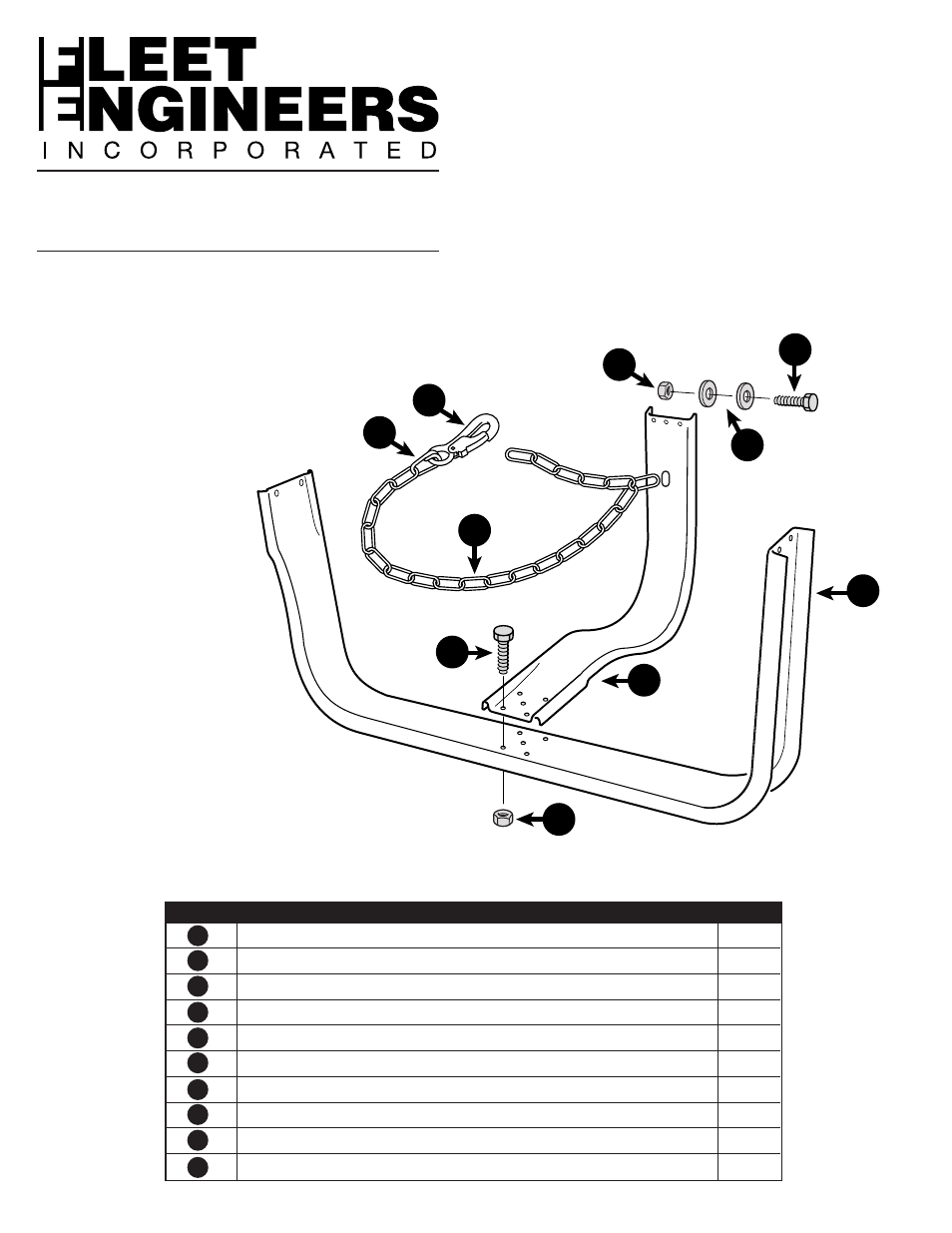
1
“U” Frame Hanger
1
2
“L” Frame Hanger
1
3
Bolt-Hex HD. 3/8-16 x 3/4
5
4
Nut - Flanged 3/8-16
5
5
Snap - Hook
1
6
Lap - Link
1
7
Link Chain - 52” Long
1
8
Bolt - Hex HD. 5/16-18 x 1
1
9
Washer - 3/4 OD x 5/16 ID x 1/16 Thick
2
10
Locknut - Hex HD. 5/16-18
1
Tire Carrier Assembly
Instruction Sheet
Installation Sheet #INS-97003
WARNING:
Loss of tire in transit can cause bodily injury or
property damage. Carry only one spare tire at
a time. Do not carry the tire loose in the carrier.
Tightly wrap the chain around the tire to elimi-
nate slack and always fasten the snap-hook to
the chain. Check regularly for bent members and
fatigue in welds and rivets. Closely examine chain,
snap-hook, and fasteners for wear, corrosion or
fatigue. Replace or repair damaged or worn parts
promptly.
ASSembly InSTruCTIonS
1. Attach
“L” Frame Hanger (#2)
to
“U” Frame Hanger (#1)
using the five (5)
bolts (#3)
and five (5)
flange nuts (#4)
provided.
2. Attach
Snap-Hook
(#5) to
Link-Chain
(#7) using
Lap-Link
(#6).
3. Slide the sixth link of the
non-hook end of chain
through the slot in the
“L” Frame Hanger (#2).
Place
bolt (#8) through link
and secure with
locknut
(#10) using
washers (#9)
1
2
3
4
5
6
7
8
9
10
ITEM
DEscrIpTIon
QTy
Installation
Sheet
#97003
3/97
•
Rev
B
2/00
•
Rev
C
1/02
•
Rev
D
2/04
•
Rev
E
12/06
10
1
2
3
4
5
6
7
8
9
"U" FRAME
HANGER
"L" FRAME
HANGER