Fleet Engineers INS-20011 User Manual
Installation instructions, Assembly instructions
Installation
Instructions
patent #6,604,724
1. thread the
TAP END (short end)
of stud into tapped hole (a) of the
bracket frame seat all the way
to the flat section using a 3/8” or
adjustable wrench on the flat sec-
tion.
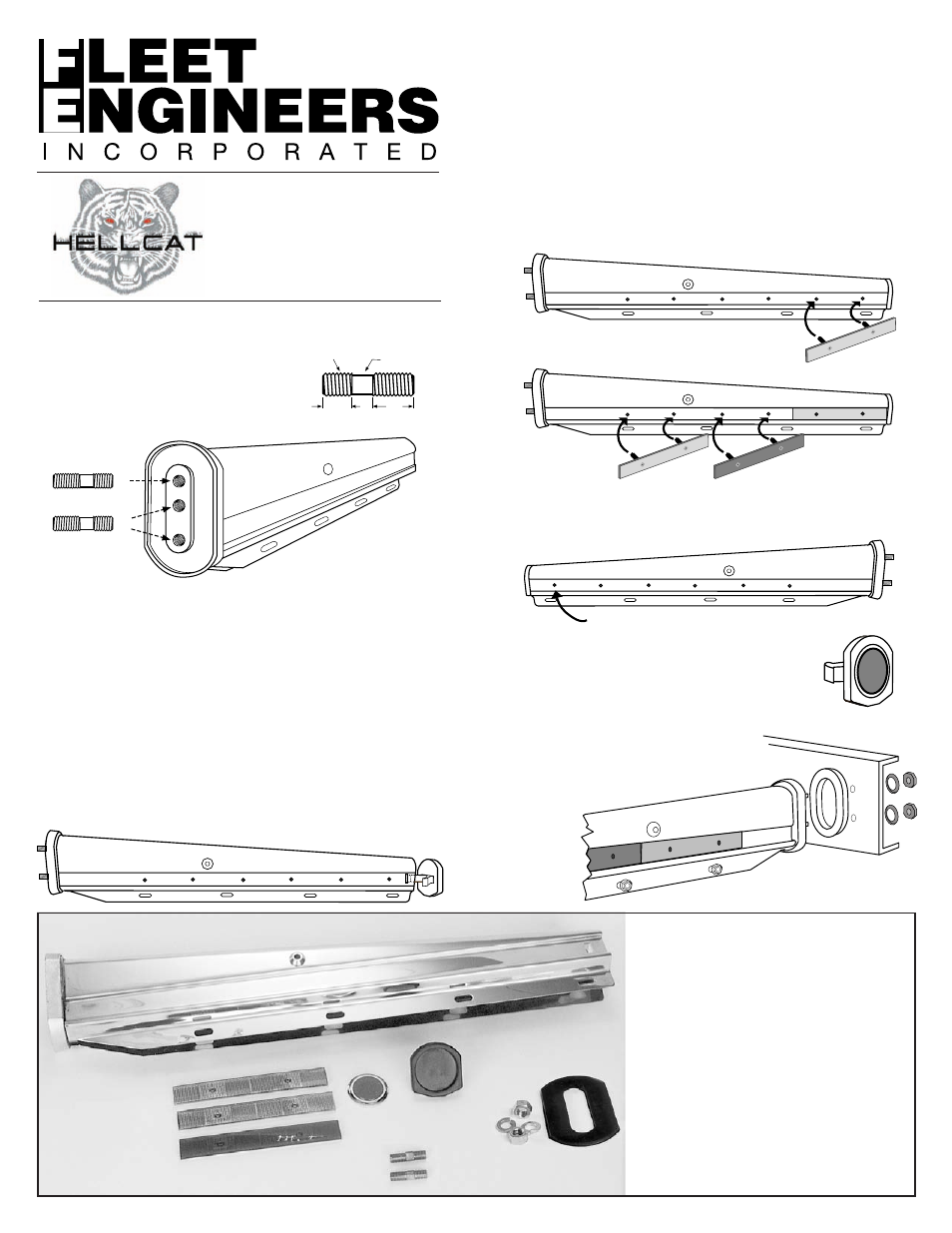
Assembly InstructIons
each HeLLCat Kit Includes
a) 2 tapered Brackets
B) 4 Mounting Studs
C) 2 anti-Vibration Gaskets
D) 2 Red Conspicuity Reflectors
e) 4 White Conspicuity Reflectors
F) 2 end Caps
G) 2 end cap Reflectors
H) 4 nuts & Lock Washers
12 nylon Snap Rivets (not shown)
12 plastic Hole plugs (not shown)
A) Tapered Bracket
B) Mounting Studs
C) Anti-Vibration
Gasket
D) Red Conspicuity
Reflector
E) White Conspicuity
Reflectors
F) End Cap
G) End Cap Reflector
H) Nuts & Lock
Washers
5.
When installing REFLECTORS, make sure the end cap and
bracket reflector recesses are clean, dry and free from any
oil or dirt. The use of a cleaning solution is recommended.
View bracket from the rear as it would be mounted on the truck and
start from the outside end. Insert two nylon snap rivets into the holes
of a white reflector. DO nOt push on the heads of the snap rivets
at this time. peel the protective strip from the adhesive backing.
Insert the rivets into the two mounting holes closest to the end of
the bracket. press the reflector in place. now push the heads of
the snap rivets firmly in. Repeat the process with the red reflector,
placing it next to the white one. Make sure to use the snap rivets
to align the reflector with the mounting holes. Do the same thing
with a white reflector, placing it next to the red one.
STUD
3/8"
Tap End
Nut End
Interference
Fit
Wrench Flat
Section
7/8"
A
B
C
A
B
C
OR
After removing protective backing from
white reflector, use rivets to find location
as shown. Press firmly in place.
Attach the red, then the next white reflector as described above.
Insert plastic hole plugs in 6 places.
6. On the opposite side of the bracket (facing tire), insert plas-
tic hole plugs into the six unused holes.
Note:
Thread locking
compound may be
used on tap end of stud
2. thread the
TAP END of the other stud in either tapped hole
(B) or (C) of the bracket frame seat all the way to the flat sec-
tion using a 3/8” or adjustable wrench on the flat section. Use
hole (B) for 1-1/8” stud/hole centers. Use hole (C) for 2-1/2
stud/hole centers.
Note: If frame thickness exceeds .50 in., the studs should be
replaced with grade 5 or better studs or bolts of appropriate
length. Make sure there is a minimum of .63 thread engage-
ment in the frame seat.
3. assemble mud flap to bracket.
4. Insert the
END CAP into the bracket one leg at a time with a
rocking motion. Make sure the clips on the cap engage the
slots in the bracket.
Installa
tion Sheet #I
NS
-2
00
11
•
6
/0
0 • Rev
. B 11/02 • Rev
. C 12/06
Installation Sheet #InS-20011
7. to install round reflector on end cap, peel
protective backing and press firmly in place.
8. place antivibration gasket in recess on frame seat of
bracket. Fasten bracket to truck
with 1/2” lock washers and nuts
torqued to 57 ft. lbs.
9. Repeat process
for the
other
bracket.
®