Fleet Engineers INS-01015 User Manual
Fleet Engineers Hardware
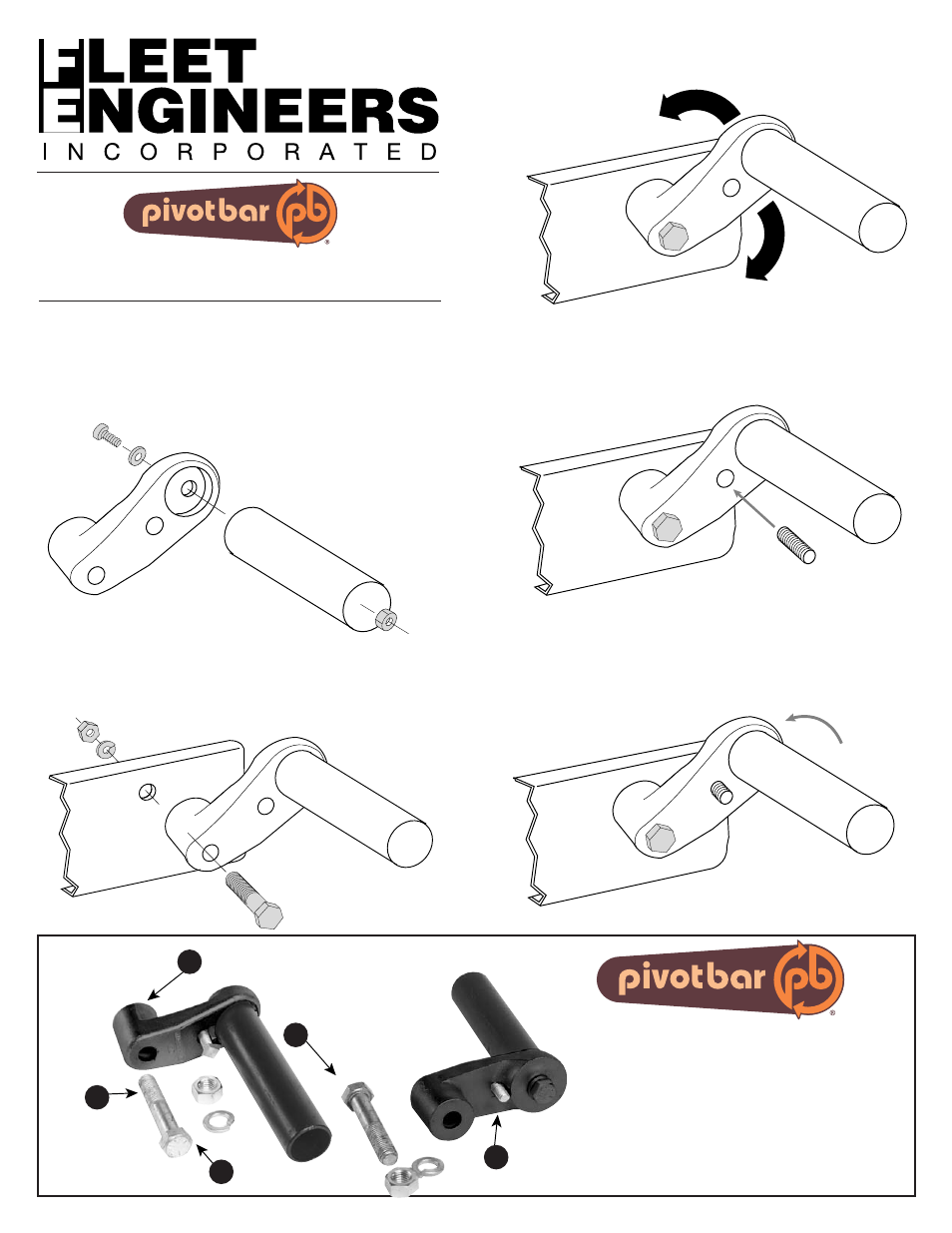
Each Standard Pivot Bar Set Includes
A) Two Pivot Bar offset mount castings
B) Two Set Screws
C) Two 3/4 x 4” Bolts
D) Two 3/4” Nuts
E) Two 3/4” Lock Washers
1. Assemble post or end mount to
Pivot Bar with appropriate class
8 hardware for your application
torqued to 245 ft. lbs for 5/8” bolts
or 425 ft. lbs for 3/4” bolts.
Installa
tion Sheet #INS-01015
11/01 • Rev
. B-12/06
3. Rotate Pivot Bar to the desired position for mounting the
fender then tighten the Pivot Bar to the frame mounting bolt
and torque to 425 ft. lbs. minimum.
BACK VIEW
FRONT VIEW
Installation Sheet #INS-01015
For Mounting Quarter and Tandem Fenders
NOTE: For some end mount applications,
it may be better to assemble loosely at
first and then torque at final assembly.
4. Thread jamming set screw into hole. Adjust it to contact truck
frame and tighten to 13-15 ft. lbs. (recommended) or until a
slight deflection of the Pivot Bar is seen).
Pivot Bar Offset Mount
Castings (2)
Sets available with or without mounts
Fenders not included
2. Select a hole in the frame for mounting. Position Pivot
Bar to hole and attach loosely with appropriate hardware
5. Tighten nut or bolt to appropriate torque (245 ft. lbs for 5/8”
bolts or 425 ft. lbs for 3/4” bolts) on end or post mount if left
loose (from step 1). Attach fender on post or end mount in
accordance to the manufacturers instructions.
Tighten Nut
Behind Mount
A
Set Screws (2)
B
3/4 x 4” Bolts (2)
C
3/4” Nuts (2)
D
3/4” Lock Washers (2)
E
NOTE: These instructions for installation are intended to be a gen-
eral guide to help the installer. Because of the large number of
possible mounting configurations, the installer is responsible
for the installation design. Any modifications to the product are
at the discretion, responsibility and risk of the installer.
PATENT
#6,471,228