Digilent XCRP User Manual
Page 5
XCRP Reference Manual
Digilent, Inc.
Copyright Digilent, Inc.
Page 5/5
Doc: 502-046
Expansion connector
An expansion connector labeled J3 on the
board edge has been provided so that designs
can easily be extended beyond the XCRP
board. The connector uses a 2 x 20, 100-mil
spaced grid so that standard headers or
sockets may easily be loaded (no expansion
connector is loaded during manufacturing to
allow greater flexibility). All available CPLD
signals are routed to the connector, including
signals that drive on-board devices. Where
feasible, on-board devices are decoupled from
the CPLD with series resistors so that all pins
may be used as inputs or outputs by the
expansion connector. VCC and GND are also
routed to the connector so that attached
devices can draw power from the XCRP board.
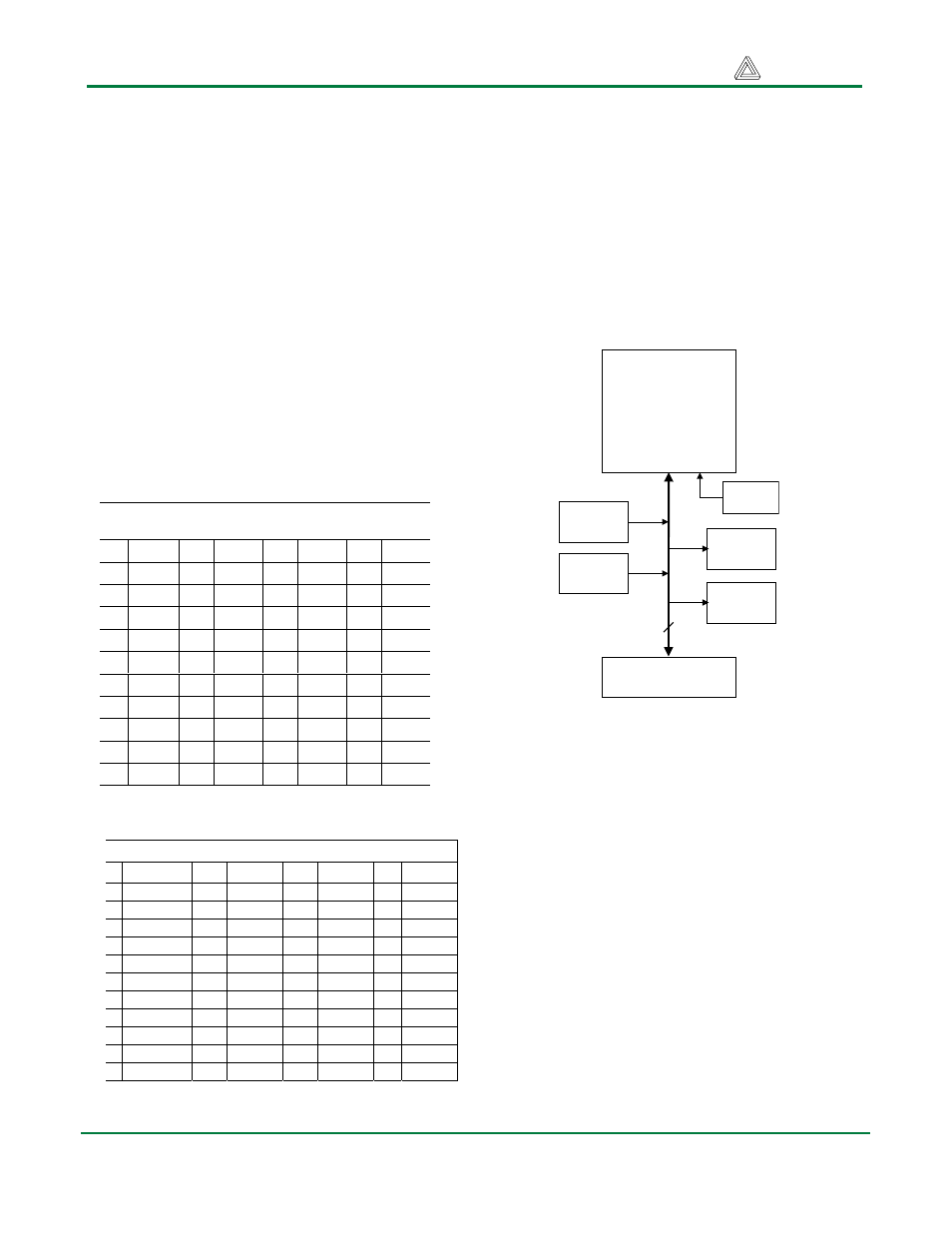
CPLD
The Xilinx CoolRunner XCR3064 CPLD on the
XCRP board uses a 44-pin PLCC package,
with four used for VCC connections, three for
GND, and five for JTAG programming. All
remaining 32 I/O pins are routed to the
expansion connector, and 31 are also routed to
on-board devices (4 for pushbuttons, 8 for slide
switches, 8 for LEDs, 10 for the seven-
segment device and one for the system clock).
The block diagram shows all connections
between the CPLD and the devices on the
board. CPLD pin connections are shown in the
following table.
The CPLD device can be configured using the
Xilinx JTAG tools and a JTAG programming
cable connecting the XCRP board and the host
computer. A Xilinx programming cable can also
be used.
The XCRP board can also accommodate a
XCR3032 CPLD. For further information on the
CoolRunner CPLD, please see the Xilinx data
sheets available at the Xilinx website
(www.xilinx.com).
Expansion
Connector
32
Xilinx
XCR3064
CoolRunner
CPLD
Slide
switches
Push
buttons
LEDs
7-seg
display
4
8
8
10
Clock
Figure 7. CPLD Connections
Table 2. Digilab XCR board expansion
connector pinout
Pin Signal Pin Signal Pin Signal Pin Signal
1 GND 11 SW4 21 AD 31 NC
2 NC 12 LED5 22 BTN2 32 SW5
3 VCC 13 NC 23 AC 33 NC
4 LED1 14 LED6 24 BTN3 34 SW6
5 SW1 15 AG 25 AB 35 NC
6 LED2 16 LED7 26 BTN4 36 SW7
7 SW2 17 AF 27 AA 37 NC
8 LED3 18 LED8 28 CAT1 38 SW8
9 SW3 19 AE 29 NC 39 NC
10 LED4 20 BTN1 30 CAT2 40 IO1
Table 3. Digilab XCR board CPLD pinout
in Signal Pin Signal Pin Signal Pin
Signal
1
BTN1
12
SW8
23 VCC 34
LED7
2
MCLK
13
TMS
24 AF 35
VCC
3
VCC
14
SW7
25 AE 36
LED5
4
BTN4
15
VCC
26 AD 37
LED4
5
SW1
16
SW6
27 AC 38
TDO
6
SW2
17
SW5
28 AB 39
LED3
7
TDI
18
CAT1
29 AA 40
LED2
8
SW3
19
CAT2
30 GND 41
LED1
9
SW4
20
IO2
31 LED8 42
GND
0 PORTEN
21
AG
32 TCK 43
BTN3
1
IO1
22
GND
33 LED6 44
BNT2