Digilent XCRP User Manual
Page 3
XCRP Reference Manual
Digilent, Inc.
Copyright Digilent, Inc.
Page 3/3
Doc: 502-046
consumes less than 80mA with all LEDs and
LED segments illuminated.
LEDs
Eight LEDs (four red, two yellow, and two
green) are provided for circuit outputs. LED
anodes are driven directly from the CPLD via
470-ohm resistors, and the cathodes are
connected directly to ground. The CPLD
connection point is also available at the
expansion connector via a 470-ohm resistor.
Three colors are offered so that circuits like
traffic light controllers or basic meters can
easily be implemented. A ninth LED is also
provided as a power-on LED.
Pushbutton
Four debounced pushbuttons are provided for
circuit inputs. Buttons are debounced with an
RC-Schmidt trigger circuit so that they may be
used as clocks for basic sequential circuits.
Button outputs (at the output of the Schmidt
trigger) are normally low, and they are driven
high only when the button is pressed. Button
outputs are available at the expansion
connector.
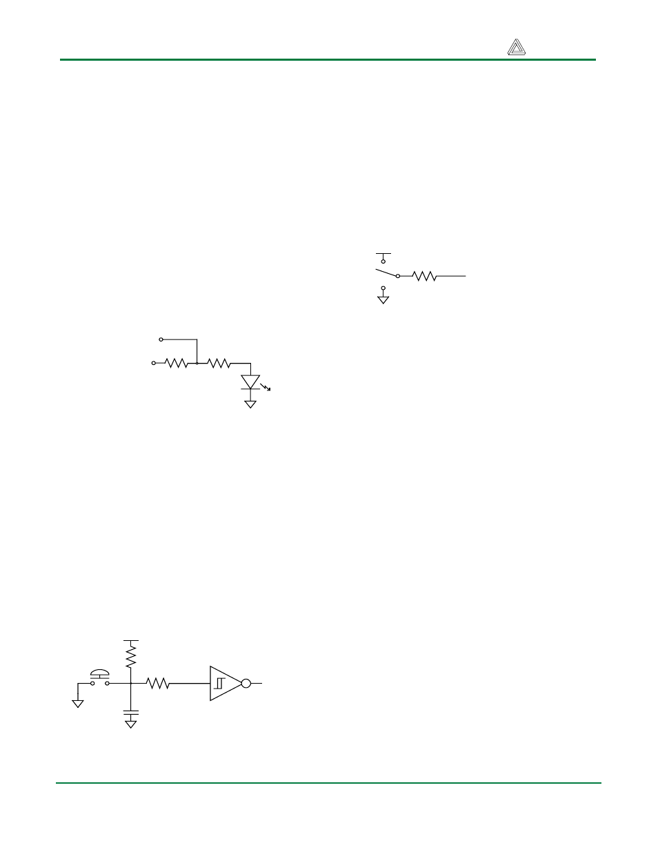
Slide Switches
Eight slide switches are provided for circuit
inputs. The slide switches use a 4.7Kohm
series resistor for nominal input protection.
Switch outputs are available at the expansion
connector.
Seven Segment Display
The XCRP board contains a modular 2-digit,
common cathode, seven-segment LED
display. In a common cathode display, the
seven cathodes of the LEDs forming each digit
are connected to a common circuit node.
On the XCRP board, the two-digit display has
two common cathode nodes labeled CAT1 and
CAT2. Both cathodes, and therefore both
digits, can be independently turned on and off
by driving the CAT1/2 signals to a ‘1’ or a ‘0’
respectively.
The anodes of similar segments on both
displays are also connected together into
seven common circuit nodes labeled AA
through AG. Thus, each anode for both
displays can be turned on and off
independently. This connection scheme
creates a multiplexed display, where driving
the cathode signals and corresponding anode
patterns of each digit in a repeating,
continuous succession can create a stable 2-
digit display.
Even though each digit is illuminated only half
time, the human eye will be “tricked” into
seeing continuously illuminated digits (this
470
ohms
Expansion
Connector
CPLD
From
470
ohms
Figure 3. LED Circuit
To CPLD
expansion
connector
4.7K ohms
0.1uF
4.7K ohms
Figure 4. Pushbutton Circuit
4.7K
ohms
To CPLD &
expansion
connector
Figure 5. Slide Switch Circuit