Digilent XCRP User Manual
Page 4
XCRP Reference Manual
Digilent, Inc.
Copyright Digilent, Inc.
Page 4/4
Doc: 502-046
phenomenon is used by all multiplexed
displays, including televisions, computer
monitors, and motion pictures). To appear
bright and continuously illuminated, both digits
should be driven once every 1 to 16ms (for a
refresh frequency of 1KHz to 60Hz). For
example, in a 60Hz refresh scheme, each digit
would be illuminated for ½ of the refresh cycle,
or 8ms.
A display controller must assure that the
correct anode pattern is present when the
corresponding cathode signal is driven. To
illustrate the process, if CAT1 is driven high
while AB and AC are driven high, then a “1” will
be displayed in digit position 1. Then, if CAT2
is driven high while AA, AB and AC are driven
high, then a “7” will be displayed in digit
position 2. If ACAT1/AB, AC are driven for
8ms, and then CAT2/AA, AB, AC are driven for
8ms in an endless succession, the display will
show “17” and the observer cannot tell that
both digits are not continuously illuminated. An
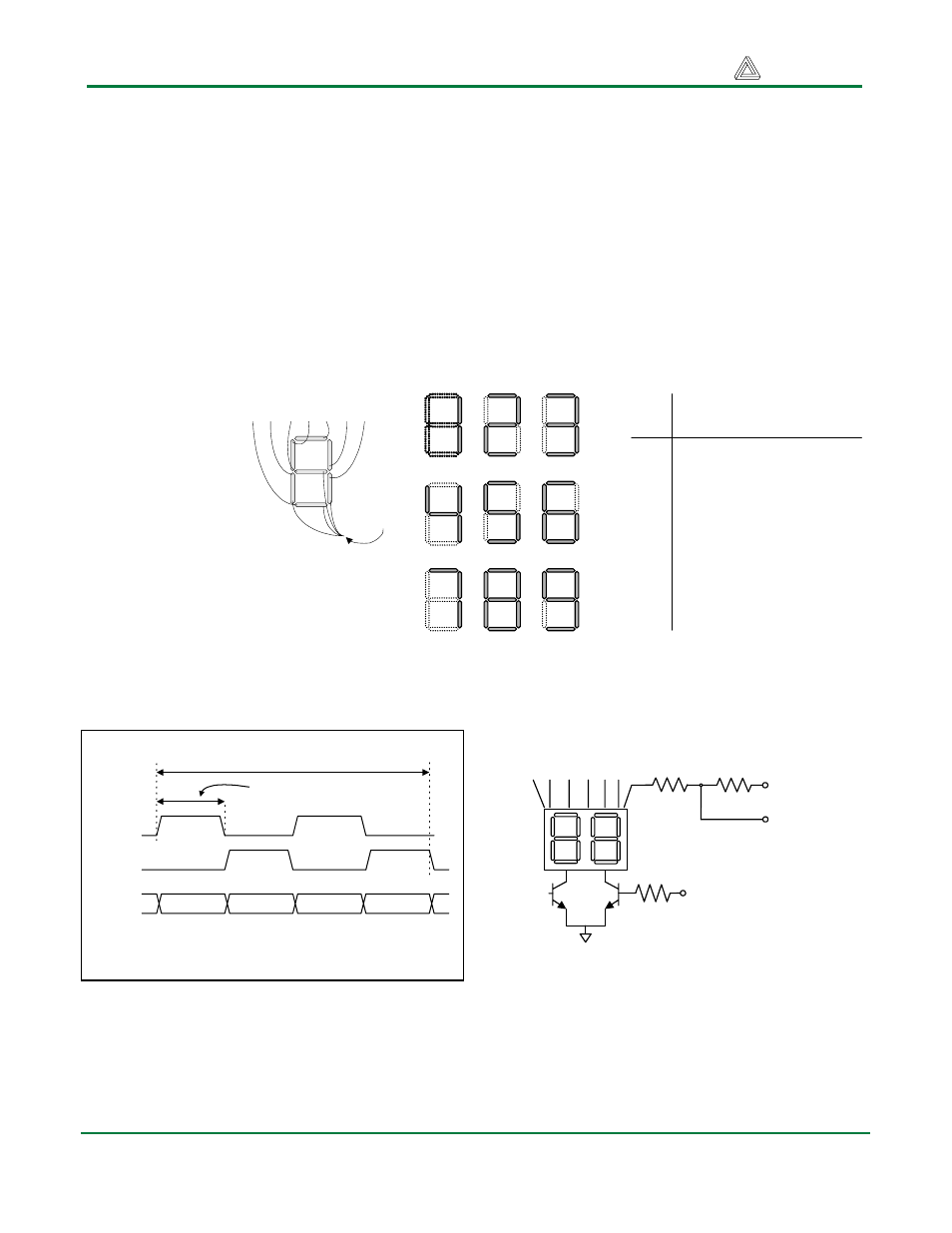
example timing diagram is provided below.
The seven-segment display anodes are driven
from the CPLD pins via 470 resistors, and the
cathodes are driven by two 2N3904 NPN
transistors to supply the required cathode
current. The 3904 bases are driven from the
CPLD via 100-ohm resistors. The CPLD
connection point is also available at the
expansion connector via a 470-ohm resistor.
Figure 7. (a) Seven segment display detail.
(b) common cathode display configuration.
(c) segement illumination patterns for decimal
digits. (d) segment illumination truth table.
Common
cathode
Digit
Illuminated Segment
Shown
a b c d e f g
0
1 1 1 1 1 1 0
1
0 1 1 0 0 0 0
2
1 1 0 1 1 0 1
3
1 1 1 1 0 0 1
4
0 1 1 0 0 1 1
5
1 0 1 1 0 1 1
6
1 0 1 1 1 1 1
7
1 1 1 0 0 0 0
8
1 1 1 1 1 1 1
9
1 1 1 1 0 1 1
a
f
g
e
d
c
b
(a)
(b)
(c)
(d)
Anodes connected to CPLD and expansion
connector via 470-ohm resistors
aa ab ac ad ae af ag
100
470
470
CAT1
CAT2
Cathodes connected to ground via two transistors
driven from the CPLD and the expansion connector
CAT1
CAT2
Anodes
Digit1
Digit2
Digit3
Digit4
Diagram showing timing requirements
Refresh period = 1 to 16ms
Digit period = Refresh / 2