Digilent 410-295P-KIT User Manual
Page 25
ChipKIT Pro MX4 Reference Manual
Copyright Digilent, Inc. All rights reserved.
Other product and company names mentioned may be trademarks of their respective owners.
Page 25 of 37
Appendix A: Connector Descriptions and Jumper Settings
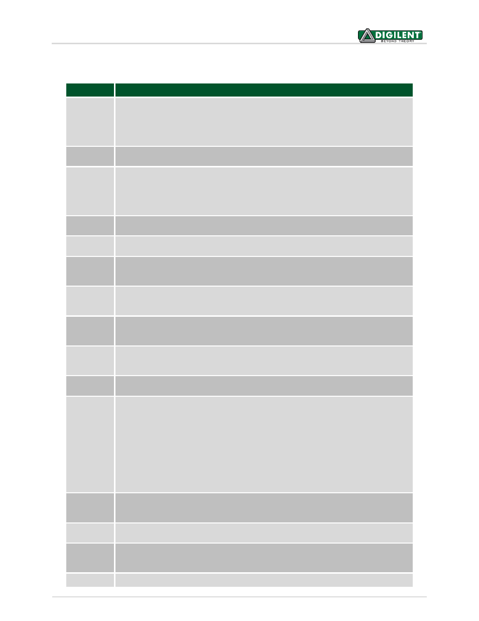
Label
Function
J1
SPI port #1 connector
Because of multiple uses for the pins, the signals for SPI port #1 are scattered across
multiple Pmod connectors. This connector provides all of the SPI port #1 signals on a single
connector. All of the signal pins on this connector are shared with pins on various Pmod
connectors.
J2
I2C port #1 daisy chain connector
This connector provides access to the I
2
C signals, power and ground for I2C1.
J3 & J4
Pull-up enable for I2C port #1
These two jumpers are used to enable/disable the pull-up resistors on I2C1. Insert shorting
blocks on these two jumpers for enable the pull-up resistors. Remove the shorting blocks
to disable the pull-up resistors. Only a single device on the I
2
C bus should have the pull-up
resistors enabled.
J5
Servo bus power connector
This connector is used to provide power to the servo power bus, VS.
J6
I2C port #2 daisy chain connector
This connector provides access to the I
2
C signals, power and ground for I2C2.
J7
USB Serial converter auxiliary signals
This connector can be used to access the auxiliary RS232 handshaking signals not used on
the ChipKIT Pro MX4 board.
J8
USB Serial converter (UART) connector
This USB micro-AB connector is used to connect the FT232R serial converter to a USB port
on the user PC.
J9
Licensed Debugger USB connector
This USB micro-AB connector is used to connect the licensed debugger to a USB port on
the user PC.
J10
DAC output
The analog output voltage of IC3, the MCP4725 Digital to Analog converter, is available at
this connector.
J11
Do not use
Used for manufacturing test purposes.
J12
Power supply source select
This jumper is used to select the source of main board power.
Place a shorting block in the USB position to have the board powered from the USB device
connector, J15.
Place a shorting block in the EXT position to have the board powered from one of the
external power connectors, J13, J14, or J18.
Place a shorting block in the DBG position to have the board powered from the debug USB
connector, J9.
Place the shorting block in the URT position to have the board powered from the USB
serial converter connector, J8.
J13
External power connector
This is a 5.5mm x 2.5mm coaxial power connector wired center positive. This is used to
supply external power to the board.
J14
External power connector
This is a two pin header connector that can be used to supply external power to the board.
J15
USB OTG connector
This is a USB micro-AB connector that is used when the ChipKIT Pro MX4 board is used to
implement a USB device, or USB OTG device.
J16
PIC32 pin 20 function select