Digilent 410-134P-KIT User Manual
Page 5
Nexys2 Reference Manual
Digilent
www.digilentinc.com
Copyright Digilent, Inc.
Page 5/17
Doc: 502-134
series resistor for protection against short circuits (a short circuit would occur if an FPGA pin assigned
to a pushbutton or slide switch was inadvertently defined as an output).
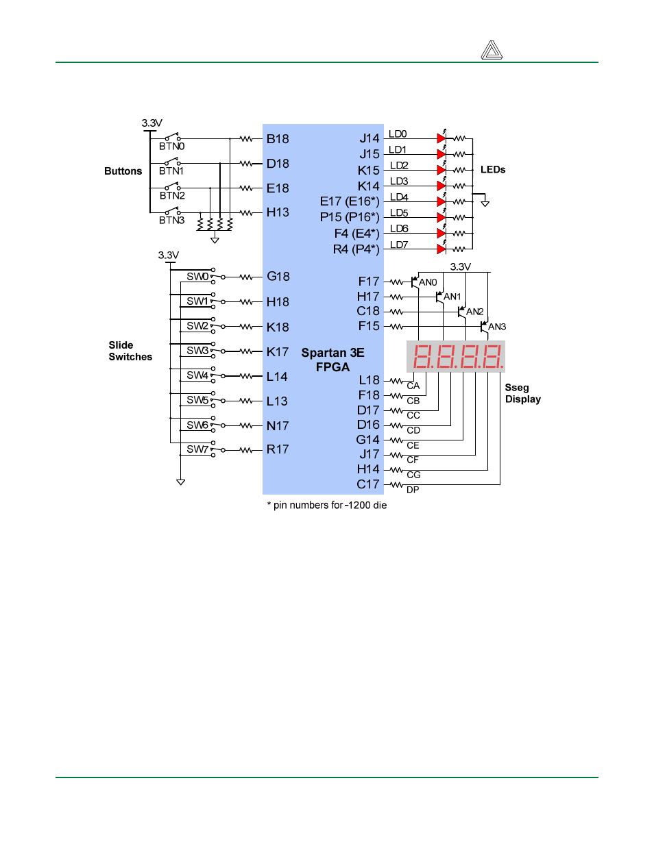
Figure 8: Nexys2 I/O devices and circuits
Outputs: LEDs
Eight LEDs are provided for circuit outputs. LED anodes are driven from the FPGA via 390-ohm
resistors, so a logic ‘1’ output will illuminate them with 3-4ma of drive current. A ninth LED is provided
as a power-on LED, and a tenth LED indicates FPGA programming status. Note that LEDs 4-7 have
different pin assignments due to pinout differences between the -500 and the -1200 die.
Outputs: Seven-Segment Display
The Nexys2 board contains a four-digit common anode seven-segment LED display. Each of the four
digits is composed of seven segments arranged in a “figure 8” pattern, with an LED embedded in
each segment. Segment LEDs can be individually illuminated, so any one of 128 patterns can be
displayed on a digit by illuminating certain LED segments and leaving the others dark. Of these 128
possible patterns, the ten corresponding to the decimal digits are the most useful.