Digilent 410-134P-KIT User Manual
Page 10
Nexys2 Reference Manual
Digilent
www.digilentinc.com
Copyright Digilent, Inc.
Page 10/17
Doc: 502-134
VGA Port
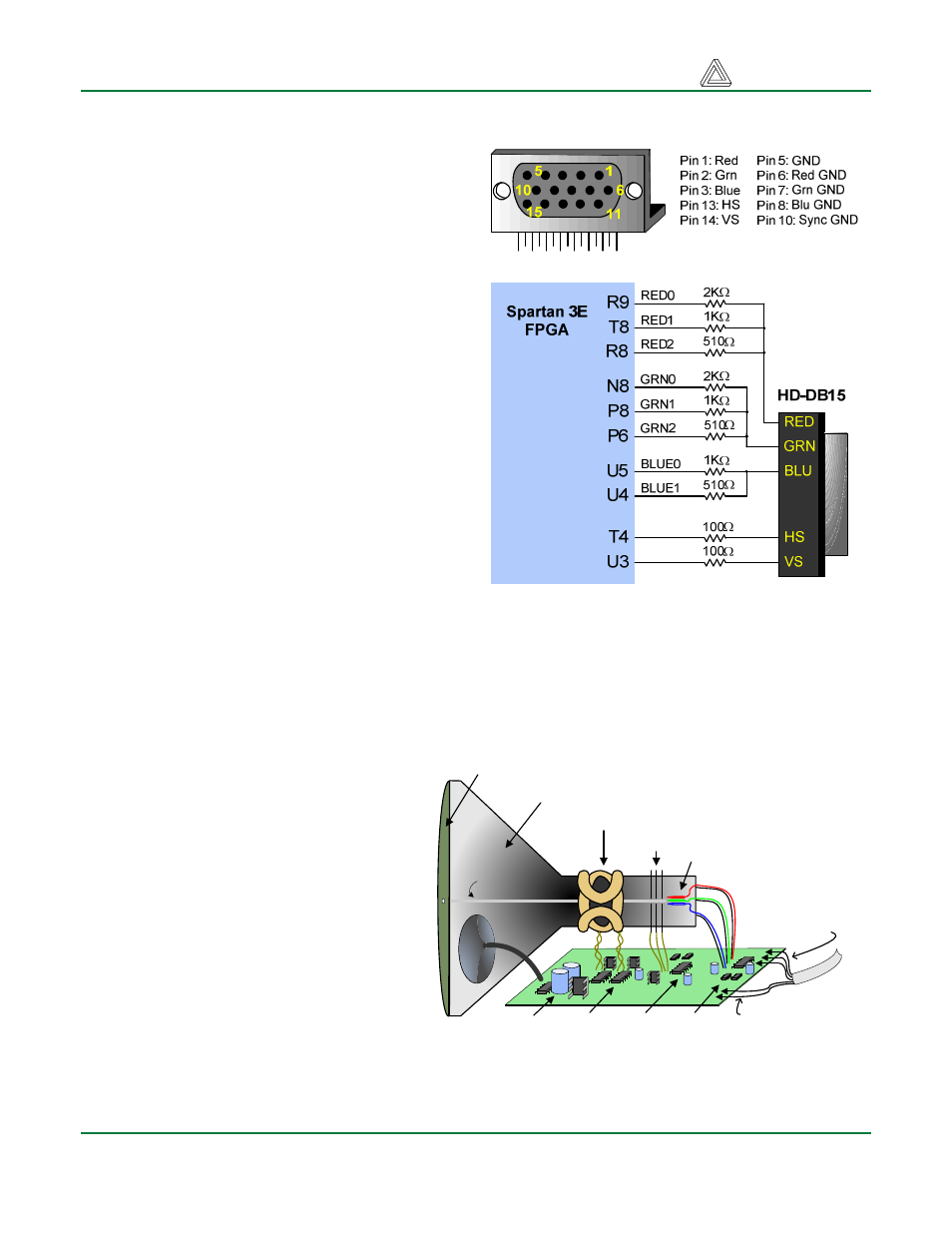
The Nexys2 board uses 10 FPGA signals to
create a VGA port with 8-bit color and the two
standard sync signals (HS – Horizontal Sync,
and VS – Vertical Sync). The color signals use
resistor-divider circuits that work in conjunction
with the 75-ohm termination resistance of the
VGA display to create eight signal levels on the
red and green VGA signals, and four on blue
(the human eye is less sensitive to blue levels).
This circuit, shown in figure 13, produces video
color signals that proceed in equal increments
between 0V (fully off) and 0.7V (fully on). Using
this circuit, 256 different colors can be
displayed, one for each unique 8-bit pattern. A
video controller circuit must be created in the
FPGA to drive the sync and color signals with
the correct timing in order to produce a working
display system.
VGA System Timing
VGA signal timings are specified, published,
copyrighted and sold by the VESA organization
(www.vesa.org). The following VGA system
timing information is provided as an example of
how a VGA monitor might be driven in 640 by 480 mode. For more precise information, or for
information on other VGA frequencies, refer to documentation available at the VESA website.
CRT-based VGA displays use amplitude-modulated moving electron beams (or cathode rays) to
display information on a phosphor-coated screen. LCD displays use an array of switches that can
impose a voltage across a small amount of
liquid crystal, thereby changing light
permittivity through the crystal on a pixel-
by-pixel basis. Although the following
description is limited to CRT displays, LCD
displays have evolved to use the same
signal timings as CRT displays (so the
“signals” discussion below pertains to both
CRTs and LCDs). Color CRT displays use
three electron beams (one for red, one for
blue, and one for green) to energize the
phosphor that coats the inner side of the
display end of a cathode ray tube (see
illustration). Electron beams emanate from
“electron guns” which are finely-pointed
heated cathodes placed in close proximity
to a positively charged annular plate called
a “grid”. The electrostatic force imposed by
the grid pulls rays of energized electrons
Figure 16: VGA pin definitions and Nexys2 circuit
Anode (entire screen)
High voltage
supply (>20kV)
Deflection coils
Grid
Electron guns
(Red, Blue, Green)
gun
control
grid
control
deflection
control
R,G,B signals
(to guns)
Cathode ray tube
Cathode ray
VGA
cable
Figure 17: CRT deflection system