Advertencia – Crosman BP2563 User Manual
Page 7
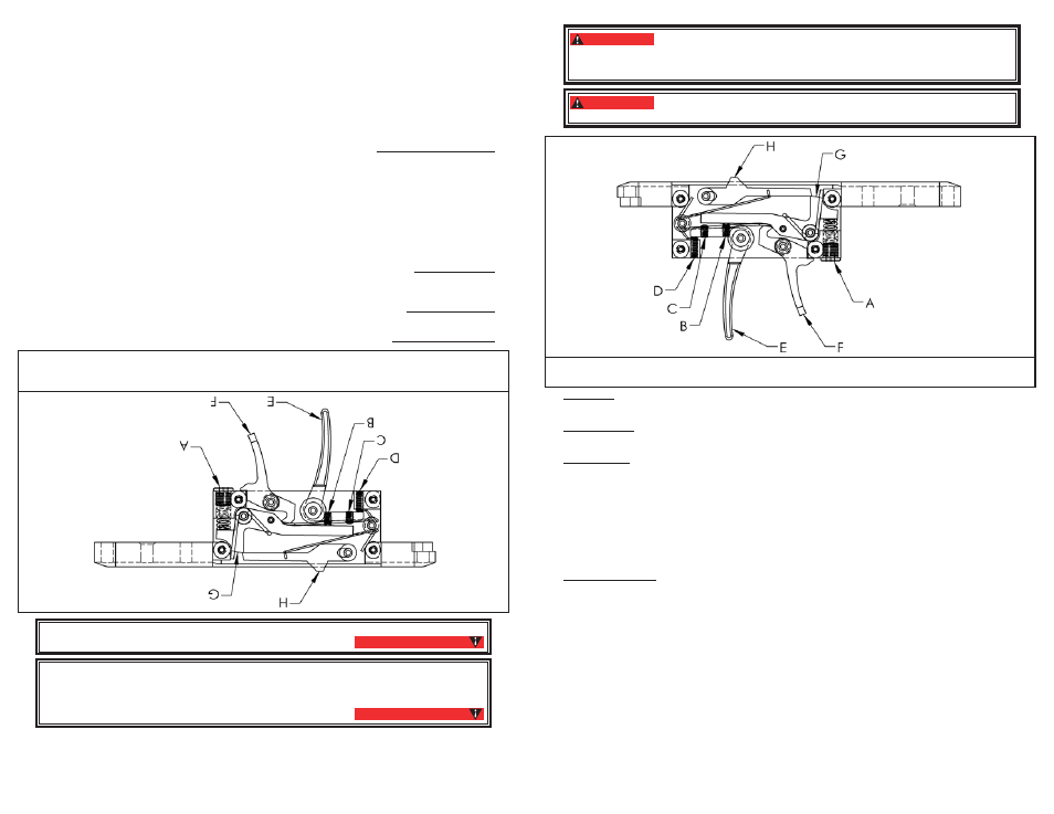
WARNING:
Adjustment of trigger screw (B) could inhibit proper function of the safety
lever (F). Thus, always check for full engagement and smooth function of the safety lever
upon completion of any changes to the trigger screw. If you are not sure if the safety is en-
gaging and operating properly, take your gun to an experienced gunsmith.
WARNING:
Adjustment to the trigger assembly could allow this airgun to fire if dropped
or jarred, with or without the safety engaged.
A. TRIGGER WEIGHT ADJUSTER B. FIRST STAGE ADJUSTER C. SECOND STAGE ADJUSTER
D. TRIGGER POSITION E. TRIGGER F. SAFETY LEVER G. LINK H. SEAR
Trigger Pull
•
Using a 1/8” Allen wrench turn the adjuster screw (A) clockwise to increase trigger pull
weight and counterclockwise to decrease trigger pull weight. This adjustment will not affect
sear engagement.
Trigger Position
•
Using a .050” Allen wrench the trigger position at rest can be adjusted. Turn screw (D)
clockwise to move the trigger back and counter clockwise to move the trigger forward. This adjustment
could affect sear engagement, and therefore could allow the gun to fire when dropped or jarred.
Trigger Stages
•
Using a .050” Allen wrench for adjustment of screws (B) and (C), changes can be made
to the position and length of first and second stages of the trigger motion. These adjustments could
affect sear engagement, and therefore could allow the gun to fire when dropped or jarred.
Screw (B) changes the first stage. Turning screw (B) clockwise will increase the length of the first
•
stage and decrease the sear engagement. Turning counter clockwise will decrease the length of
the first stage and increase the sear engagement.
Screw (C) changes the second stage. Turning screw (C) clockwise will cause the second stage to
•
occur sooner while turning counterclockwise will cause the second stage to occur later.
Adjustment of screws (B) and (C) should be done in harmony with each other as they work
•
together to create the trigger’s profile. Start slowly to understand what each adjustment does and
its relationship to the other.
Trigger Maintenance
•
The trigger is assembled with a moly graphite EP grease that should last for years.
In the event your trigger becomes contaminated with debris and is not functioning properly, contact a
qualified gunsmith to examine for repair or maintenance.
After adjusting your trigger, always check that the trigger and safety are functioning properly. If you are
•
not sure if the trigger or safety is operating properly, take your gun to an experienced gunsmith.
Re-insert the action into the stock, and replace and tighten the stock screw.
•
B. Adjusting for Various Fill Pressures
The Marauder is designed to be tuned to work at various fill pressures from 2000 psi (138 bar) up
•
to 3000 psi (207 bar). This is done by adjustment of the hammer spring preload and hammer stroke
length. In either case the adjustment changes the amount of energy the hammer generates when strik-
ing the valve. Higher fill pressures require more hammer energy while lower fill pressures require less
hammer energy.
It is advised to always record your settings when tuning your airgun.
(See Page 10)
The Marauder has been factory set to an efficient fill pressure that will suit most hunting and target
•
uses. If you, as the owner, wish to alter the factory settings you should do so only after reading the fol-
lowing instructions carefully.
• El
gatillo
de
calidad
de
competencia
de
su
rifle
de
air
e de
diábolos
es
una
unidad
de
dos
etapas
totalmente
ajust
-
able. Se
ha
ajustado
de
fábrica
a
un estado
eficiente
que
será
adecuado
para
la
mayoría
de
los
usos
de
cacería
y
tiro
al blanco.
Si
usted,
como
pr
opietario, desea
alterar
los
ajustes
de
fábrica,
debe
hacerlo
únicamente
después
de leer cuidadosamente las siguientes instrucciones.
• Active
el
segur
o del
rifle
de
air
e (“ON
SAFE”),
quite
el
cargador
y
mantenga el
rifle
apuntado
en
una
DIRECCIÓN
SEGURA. Despr
esurice el
rifle
de
air
e (vea
la
sección
4)
El ajuste del tornillo del gatillo (B) podría impedir la función
adecuada de la palanca del seguro (F). Por tanto, compruebe siempr
e el enganche completo
y el funcionamiento suave de la palanca del seguro al finalizar cualquier cambio en estos
tornillos de ajuste. Si no está segur
o de que el seguro se esté enganchando y funcionando
correctamente, lleve su arma a un armer
o experimentado.
ADVERTENCIA:
Los ajustes al conjunto del gatillo podrían hacer que este rifle de
aire se dispar
e al caer o al sacudirse, con o sin el seguro puesto.
ADVERTENCIA:
A. AJUST
ADOR DEL PESO DEL GATILLO
B. AJUST
ADOR DE LA PRIMERA ETAP
A
C. AJUST
ADOR DE LA SEGUNDA ETAP
A
D. POSICIÓN
DEL
GA
TILLO
E.G
ATI
LLO
F . P
ALANCA DEL SEGURO
G. ESLABÓN
H. FIADOR
•
Resistencia del gatillo Con una llave Allen de 1/8” gir
e el tornillo de ajuste (A) en el sentido de las manecillas
del reloj para aumentar la fuerza de r
esistencia del gatillo y en sentido contrario al de las manecillas del reloj para
disminuir la
fuerza
de
resistencia
del
gatillo.
Este
ajuste
no
afectará
el
enganche
del
fiador
.
•
Posición del gatillo C
on
una
lla
ve
Alle
n d
e .0
50”
se
pu
ede
aj
ust
ar l
a p
osi
ció
n d
el g
atil
lo
en
des
can
so.
G
ire
el
tornillo
(D)
en
el
sentido
de
las
manecillas
del
reloj
para
mover
el
gatillo
hacia
atrás
y
en sentido
contrario
a
las
manecillas del
reloj
para
moverlo
hacia
delante.
Este
ajuste
podría
afectar
el
enganche
del
fiador
, y
por
tanto
podría hacer
que
el
rifle
se
dispar
e al
caerse
o
sacudirse.
•
Etapas del gatillo Con una llave Allen de .050” para los tor
nillos (B) y (C), se pueden hacer cambios a la
posición y
longitud
de
la
primera
y
segunda etapas
del
movimiento
del
gatillo.
Estos
ajustes
podrían
afectar
el
enganche del
fiador
, y
por
tanto
podrían
hacer
que
el
rifle
se
dispar
e al
caerse
o
sacudirse.
• El
tor
nillo (B)
cambia
la
primera
etapa.
Girar
el
tor
nillo (B)
en
el
sentido
de
las
manecillas
del
reloj
aumentará
la longitud
de
la
primera
etapa
y
disminuirá el
enganche
del
fiador
. Girarlo
en
sentido
contrario
al
de
las
man
-
ecillas del
reloj
disminuirá
la
longitud
de
la
primera
etapa
y
aumentará el
enganche
del
fiador
.
• El
tor
nillo (C)
cambia
la
segunda
etapa.
Girar
el
tor
nillo (C)
en
el
sentido
de
las
manecillas
del
reloj
hará
que
la
segunda etapa
ocurra
más
rápido,
mientras
que
girarlo
en
sentido
contrario
al
de
las
manecillas
del
reloj
hará
que la
segunda
etapa
ocurra
después.
• El
ajuste
de
los
tor
nillos (B)
y
(C) debe
hacerse
en
armonía
uno
con
otr
o, ya
que
trabajan
unidos
para
crear
el
perfil
del
gatillo.
Empiece
lentamente
para
entender
lo
que
hace
cada
ajuste
y
la r
elación que
tiene con el otro.
• Mantenimiento del gatillo
El
ga
tillo
es
tá
ens
am
bla
do
con
un
a g
ras
a E
P d
e m
oly
gra
fito
qu
e d
ebe
du
rar
añ
os.
En
cas
o d
e q
ue
el g
atill
o s
e c
ont
am
ine
co
n d
ese
cho
s y
no
es
té
fun
cio
nan
do
ade
cua
dam
ent
e, c
om
uní
que
se
con
un
armero calificado para que lo examine y haga las r
eparaciones o mantenimiento necesarios.
Después de
ajustar
su
gatillo,
siempr
e compruebe
que
el
gatillo
y
el segur
o estén
funcionando
corr
ecta-
men
te.
S
i n
o e
stá
se
gur
o d
e q
ue
el g
atil
lo
o e
l s
egu
ro
est
án
fun
cio
nan
do
cor
rec
tam
ent
e, l
lev
e s
u a
rm
a a
un
arm
ero
ex
per
im
ent
ado
.
Guarde el rifle de air
e en un sitio seguro.
• Antes
de
guar
dar su
rifle
de
air
e, extraiga
el
cargador
, asegúr
ese de
que
no
haya
diábolos
en
la
recámara
y
de
que el
rifle
no
esté
amartillado
(vea
la
sección
6).
• Guar
de este
rifle
de
air
e cargado
con
air
e comprimido
o
CO
2
para
mantener
las
válvulas
cerradas
contra
la
suciedad.
7
7