Building an rs-485 test cable, Building null- modem cables, Building straight- through cables – Comtrol DM ATS-LNX User Manual
Page 17: Testing serial ports, Lcom(1), File transfer, Lcom(1) file transfer
PC104 RocketPort Option
17
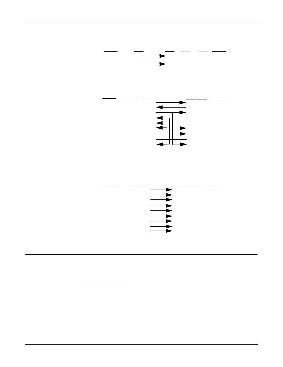
Building an RS-485 Test Cable
Building an RS-485
Test Cable
You can use a straight-through cable as illustrated previously, or build your own
cable.
Building Null-
Modem Cables
Use the following figure if you need to build a null-modem cable. A null-modem
cable is required to connect the CONSOLE port to a PC COM port or to connect
DTE devices.
Note: You may want to purchase or build a straight-through cable and purchase a
null-modem adapter.
Building Straight-
Through Cables
Use the following figure if you need to build a straight-through cable. Straight-
through cables are used to connect DCE devices.
Testing Serial Ports
You can use the following subsections to test the PC104 serial ports.
lcom(1)
Comtrol has available lcom(1), which is a multiport serial I/O test program. You
can use lcom in test mode to send test data to any ATS-LNX serial port. See
on Page 60 for information on how to use lcom.
File Transfer
You can transfer a file using the following information. The default settings are
9600, 8, n, 1, and no parity.
To send a file you can redirect output to a device; for example:
Cat /etc/inittab > /dev/ttyR0
Sends the contents of the /etc/inittab file to the ttyR0 device at 9600 baud, 8, n, 1,
and no parity.
DB9
3
7
Pins
TxD or TRX-
RTS or TRX+
Signal
TxD or TRX-
RTS or TRX+
Signal
RJ45
4
1
Pins
RJ45
4
1
Pins
DB25
2
4
Pins
AT
S
F
e
m
a
le
TxD
RxD
RTS
CTS
DSR
GND
DCD
DTR
Signal
RxD
TxD
CTS
RTS
DTR
GND
DCD
DSR
Signal
DB9
2
3
8
7
4
5
1
6
Pins
DB25
3
2
4
7
8
6
Pins
RJ45
4
5
1
8
7
3
6
2
Pins
20
5
RI
N/A
9
22
RI
DB9
3
2
7
8
6
5
1
4
Pins
9
RJ45
5
4
1
3
6
7
Pins
2
8
N/A
DB25
2
3
4
5
6
7
8
20
Pins
22
PC
C
O
M
P
o
rt
AT
S
Fe
m
a
le
DB9
1
2
3
4
5
8
6
7
Pins
DCD
RxD
TxD or TRx-
DTR
GND
CTS
DSR
RTS or TRx+
Signal
DB9
1
2
3
4
5
8
6
7
Pins
DCD
RxD
TxD or TRx-
DTR
GND
CTS
DSR
RTS or TRx+
Signal
RI
9
9
RI
RJ45
6
5
4
2
3
8
7
1
Pins
N/A
RJ45
6
5
4
2
3
8
7
1
Pins
N/A
DB25
8
3
2
20
7
5
6
4
Pins
22
De
v
ice