Vox gain control, G) delay control, G) anti-vox control – Kenwood TS-130SE User Manual
Page 8: Note, Fix indicator, 8) vfo indicator, 2 rear panel, 0 ant (antenna) connector, D gnd (ground) terminal, D cw key jack
Attention! The text in this document has been recognized automatically. To view the original document, you can use the "Original mode".
®
vox
GAIN CONTROL
This control adjusts VOX circuit sensitivity for both SSB and
CW operation.
(g) DELAY CONTROL
This control is used to adjust the "Hold" time of the VOX cir
cuit. Clockwise adjustment gives longer hold-time.
(g) ANTI-VOX CONTROL
This control is used to adjust the VOX system so that it is not
tripped by sound from the speaker.
NOTE:---------------------------------------------------------------------------
The VOX control panel (and serial number plate) is covered
by thin plastic brotective film which may be beeled off and
discarded. It is provided to protect the panel during ma
nufacture, and is not intended as a permanent part of the
radio.
® FIX INDICATOR
The FIX indicator illuminates when the internal fixed
frequency oscillator controls transceiver operation.
(8) VFO INDICATOR
The VFO indicator illuminates when the internal VFO
controls transceiver operation. The indicator is not lighted
during fixed channel or remote VFO operation.
0ANT CONNECTOR
)GND TERMINAL
I
EXT VFO CONNECTOR
-(4) SPEAKER JACK
REFERENCE FREQUENCY
ADJUSTMENT ACCESS
(D REMOTE CONNECTOR
0DC POWER CONNECTOR
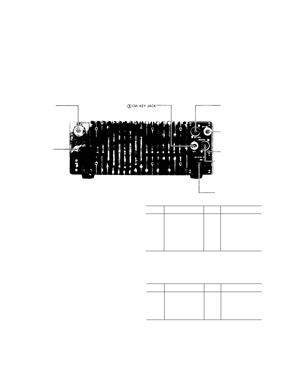
Fig 3-2 Rear. Top Panel
3.2 REAR PANEL
0 ANT (ANTENNA) CONNECTOR
This UHF connector should be attached to a suitable anten
na for transmitting and receiving. The antenna cable should
be 50-ohm coax, terminated with a PL-259 connector.
(D GND (GROUND) TERMINAL
The TS-130SE should be grounded through this terminal
to avoid the possibility of TVI and BCI. Use as short and
heavy a lead as possible.
(D CW KEY JACK
For CW operation, connect your key to this terminal using a
two conductor phone plug and shielded cable.
0 SPEAKER (EXTERNAL SPEAKER) JACK
An external speaker of 4 ~ 16 ohms impedance (such as
the SP-120) can be connected here. This will disable the in
ternal speaker.
(D
REMOTE CONNECTOR
This connector is used to interconnect a linear amplifier or
other accessory item.
PIN
FUNCTION
PIN
FUNCTION
1
Record output
5
Normally closed
2
Relay common
(relay contact)
terminal
(NOT grounded)
6
ALC input
AlC threshold level
3
PTT line
approx. — 6V
4
Normally opened
(relay contact)
7
No connection
® EXT VFO (EXTERNAL VFO) CONNECTOR
This is for connection of an external VFO-120, or remote
Frequency Controller DFC-230. (Note: the VFO-520 and
VFO-820 cannot be used, since their operating frequency is
incorrect.)
PIN
FUNCTION
PIN
FUNCTION
1
VFO signal
5
VFO control
2
Relay control
( +
on transmit)
6
Display control
3
-F9V
7
Ground
4
CW freq. shift control
8
+ 12V
0 DC POWER CONNECTOR
This is used to connect the DC power supply.
® REFERENCE FREQUENCY ADJUSTMENT (SIDE)
For PLL reference oscillator adjustment. Use WWV signal
for calibration.