1 interconnection, Fig. 2-1 [a] ts-130se interconnection, Interconnection – Kenwood TS-130SE User Manual
Page 5
Attention! The text in this document has been recognized automatically. To view the original document, you can use the "Original mode".
SECTION 2. PREPARATION FOR USE
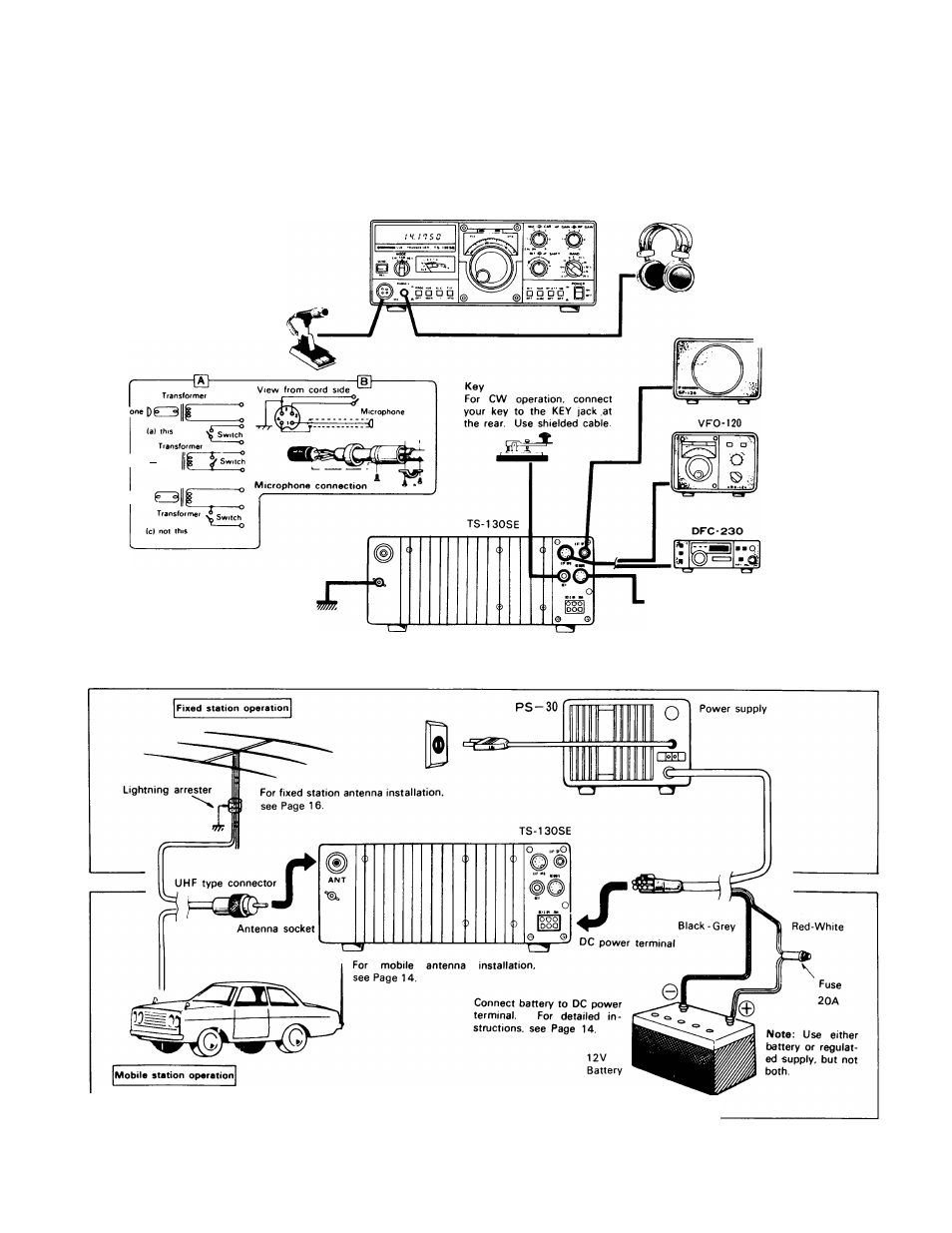
'4||||l«l||||»*4||||».4mil- 2.1 INTERCONNECTION Connect the transceiver as illustrated in Fig. 2-1. Microphone ance microphone (50012 to should be isolated from the mic circuit (shown in TS-130SE Microph Ircrophone [)(» (b) noi this Microphone 0 GND terminal terminal at the rear of the set to and heavy a lead as possible Fig. 2-1 [A] TS-130SE Interconnection Headphones Use headphones of 4 to 1612 6,5.4 headphone is best suited for use with the TS-130SE. also be used. External speaker SP-120 speaker, an external =^speaker can also be used Connect to the External VFO VFO-820 cannot be Frequency Controller The DFC-230 incorpo at 20 Hz step, and 4 memory permitting remote frequency control. REMOTE connector External accessories can be con the REMOTE connector. The PTT control of send/receive operation Fig. 2-1 [B] Antenna and Power Supply Connection for TS-130SE
Either a low or high imped
50ki2) can be used. The P.T.T.
switch
"a") Use a microphone with
a separate switch and MIC
line so both P.T.T. and VOX-
are available.
It is recommended that a ground
lead be connected to the GND
prevent the possibility of electric
shock. TVI and BCI. Use as short,
impedance. The optional HS-
Stereo type headphones can
Besides the built-in
rear EXT SP jack using
the supplied plug.
For connection of ex
ternal VFO-120
Note: VFO-520 and
used
DFC-230
rates a digital VFO
operating
channels
nected to the TS-130SE through
terminal can be used for remote