10 digital display calibration (fig. 4-14), 11 analog dial calibration, Fig. 4-15) – Kenwood TS-130SE User Manual
Page 17: Sections. additional information, 1 general information, 2 installing the optional filters, Digital display calibration, Analog dial calibration, Section 5. additional, Information
Attention! The text in this document has been recognized automatically. To view the original document, you can use the "Original mode".
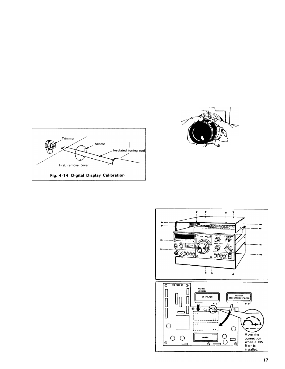
4.10 DIGITAL DISPLAY CALIBRATION
(Fig. 4-14)
4.11 ANALOG DIAL CALIBRATION
(Fig. 4-15)
Connect the antenna and set the BAND switch to 10.
Turn the main tuning dial to about "0" to receive the 10
MHz WWV signal. Adjust the dial until a low-frequency
beat is heard. Next, turn on the CAL switch and a marker
signal is superimposed on the WWV beat signal. A double
beat (two beat signals of high and low freqencies) will now
be heard.
While receiving this double beat, adjust the Counter unit
trimmer through the reference frequency adjustment access
opening (at the side of the TS-130SE so the two beats are
heard as a single beat. This completes calibration of the
Digital Display. After calibration turn off the CAL switch.
The main dial scale is graduated at 1-kHz intervals. One
revolution of the main dial covers 25 kHz. To calibrate the
scale, turn the CAL switch ON and in SSB mode zero-beat.
Hold the main tuning knob from rotating and slip the ca
libration ring to the nearest major (5 kHz) graduation. The
dial is now calibrated.
Note:
For exact frequency, read the Digital Display.
Pointer
Hold main dial
Turn Calibration ring
Fig. 4-15 Analog Dial Calibration
SECTIONS. ADDITIONAL INFORMATION
5.1 GENERAL INFORMATION
Your TS-130SE has been factory aligned and tested to
specification before shipment. Under normal circumstances,
the transceiver will operate in accordance with these
operating instructions.
If your transceiver fails to work, contact the authorized
dealer from whom you purchased it for quick, reliable repair.
All adjustable trimmers and coils in your transceiver were
preset at the factory and should only be readjusted by a
qualified technician with proper test equipment.
Attempting service or alignment without factory authoriza
tion can void the transceiver's warranty
5.2 INSTALLING THE OPTIONAL FILTERS
1. Using a # 2 philips screwdriver, remove the top cover (8
screws). Be careful of the VOX controls, and the
speaker lead, which may be unplugged.
2. Remove the bottom cover (7 screws).
3. Remove 7 screws from the IF unit and swing the board
up and towards the center of the radio.
4. Using a 45W (or less) soldering pencil, clear the 6 holes
for the filter, if they are filled with solder.