3 ts-130se analog dial adjustment, 4 howthetxfinaltransistors are protected, 5 transmitting on warc bands – Kenwood TS-130SE User Manual
Page 18: 6 phone patch operation, 7 ordering spare parts
Attention! The text in this document has been recognized automatically. To view the original document, you can use the "Original mode".
5. There is no polarity to the filter. Install the filter into its
position on the IF unit. Solder the 2 mounting tabs,
and the 4 input and output pins to the circuit board.
Solder sparingly, and heat the connections only long
enough to insure a good solder joint. Don't overheat
the filter or circuit board.
6. Carefully inspect your soldering. Be certain that all
pins are actually soldered, and that you have not
soldered across any spots on the board or between any
of the pins on the filter. Clip the pins fluse to the board.
7. Replace the IF unit in its place. Make certain no wires
will be pinched underneath the board. Replace the 7
screws.
8. Move the connection as illustrated when a CW filter is
installed.
9. Reinstall the bottom cover. Reconnect the speaker
lead, and reinstall the top cover.
10. Apply power and verify your work. Filter installation is
now complete.
5.3 TS-130SE ANALOG DIAL ADJUSTMENT
1. Turn the main dial fully CCW. The red cursor should line
up with the VFO start mark on the sub-dial. If it does
not, remove the main knob (2mm Allen), loosen the 12
mm nut and line up the scale start point to the red
cursor.
2. Turn the main knob to 50 kHz analog. Adjust the alumi
num slip sub-dial to line up with any one of the larger
black dial marks.
3. Note the digital error. If it is MORE than 2 kHz adjust
the VFO trimmer cap TCI (front under the seal tape) to
exactly 50.0 on the digital readout.
4. Turn the main knob to 450 analog. If the digital error is
less than 2 kHz it is in spec. If the digital error is
greater, proceed:
For instance if the digital error is 14.454.0 (plus 4 kHz),
multiply the error times 4 ( 1 6 kHz) and adjust the VFO
trimmer cap to the desired frequency (14.450.0) LESS
the error, or 14.434.0. Next adjust the VFO inductor
L3 (center under the seal tape) back up to the desired
frequency of 14.450.0.
5. If the error in step 4 was in the minus direction, reverse
the direction of correction adjustment in step 4.
6. VFO linearity final check; The digital readout and
analog dial should agree to within ±2 kHz at every 100
kHz dial point.
5.4 HOWTHETXFINALTRANSISTORS ARE
PROTECTED
Final transistor protection is provided by sampling the
reflected power. As the reflected power is increased (higher
SWR) transmitter drive is reduced, thus decreasing input to
the final transistors. This in turn reduces collector loss,
protecting the final transistors.
5.5 TRANSMITTING ON WARC BANDS
As supplied, the TS-130SE will receive but not transmit on
the 3 new WARC bands. If transmit capability is desired, a
minor wiring change is required.
1. For all 3 bands; On the Rf unit X44-1380-00 unplug
J5 (or cut the brown wire).
2. Of for individual Bands; On the RF unit:
Band
Remove (orcut) Part
10 MHz
18 MHz
24.5 MHz
D8
D9
DIO
5.6 PHONE PATCH OPERATION
The PC-1 Phone Patch may be used with the TS-130SE.
Recommended settings are:
PC-1
RX Gain 4
TX Gain 4
Null as necessary
TS-130SE Vox Gain 1
AF Gain 4
Mic Gain 5
Anti Vox Max
Most other phone patches will work satisfactorily without
any modification to the radio, requiring only an external
speaker connection, and that the Mic line be run through the
patch.
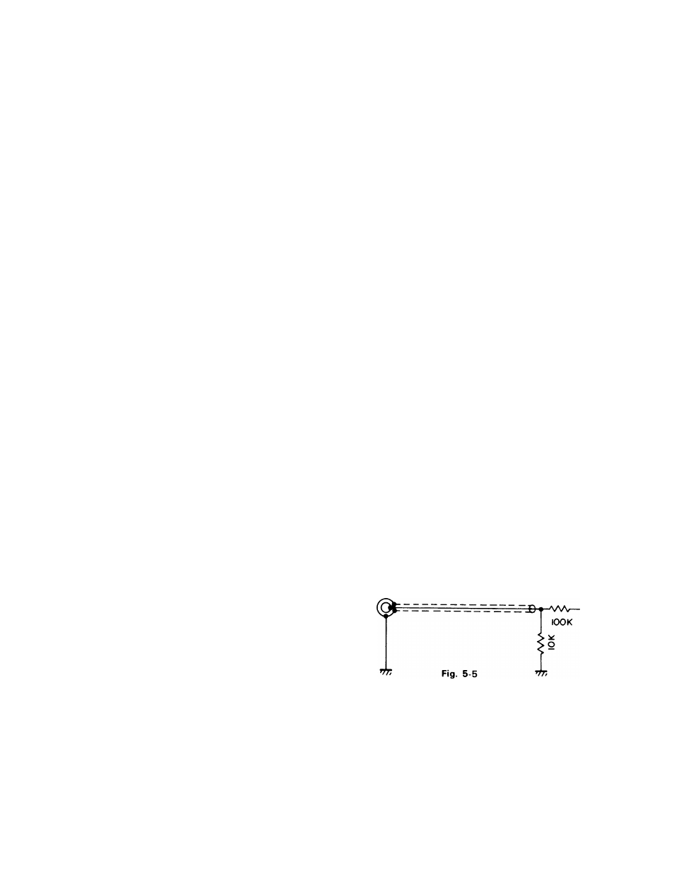
For those oprators who desire a Patch input similar to the
TS-520SE or TS-820S, an input connection and terminal
must be added at the Mic input preamp circuit.
Use a 100-Ki2 resistor in series, with a 10-ki2 to ground on
the input side of the 100-ki2 resistor. Use shielded line, and
connect as follows:
On the AF Gen unit X49-1110-01 install the fixed divider at
the junction of R43 10k, C42 lOOpf, and C43 luF (input of
Q18). Add an RCA jack, or use remote pins 7 and Gnd for
input.
Input
5.7 ORDERING SPARE PARTS
When ordering replacement or spare parts for your equip
ment, be sure to specify the following:
• Model and serial number of your transceiver. Schematic
number of the part. Printed circuit board number on
which the part is located. Part number and name, if
known, and Quantity desired.
NOTE: --------------------------------------------------------------------- -----
A full service manual is available as a separate publication.
18